|
home /
infca /
arduino
(navigation links)
|
This song touches my heart like a wild spirit |
Nano specs
|
Nano pinout
|
Uno specs ,
Holtek HT42B534-2
IDE,
language specs,
Arduino concepts :
program structure,
language reference,
sensitive data,
code origin and timestamp ;
how to debug,
init Serial,
connect to wifi,
concatenate strings,
String parameter
code samples :
talk with rspi
|
ACS712, sensor de intensistat per efecte Hall
|
minicom,
rshell
|
2x nrf24
|
KY-037 i KY-038
Albert's ESP32 TTGO -
color test,
read BTC value +
connect to wifi,
code to GitHub,
send to bot,
we are bot,
use NTP
|
micro python :
.bin file,
RTC,
display directory,
*** connect wifi ***,
display REE,
display NTP clock
|
dubtes
Ramon's ESP32 WROOM32 -
connect wifi,
log data into Google Sheets,
send to TG bot,
receive from TG bot
|
caixetes
|
Links
|
End
|
mapa 
|
Arduino
go 2 top
ESP 32
The ESP32 is a series of chip microcontrollers developed by Espressif.
Arduino core for the ESP32 {****}
ESP 32 specs
ESP32 Features and Specifications
Here’s a quick run down of some features and specifications of the ESP32 chip:
Wireless connectivity WiFi: 150.0 Mbps data rate with HT40
Bluetooth:
BLE (Bluetooth Low Energy) and
Bluetooth Classic
Processor: Tensilica Xtensa Dual-Core 32-bit LX6 microprocessor, running at 160 or 240 MHz
ROM: 448 KB
SRAM: 520 KB
Low Power: ensures that you can still use ADC conversions, for example, during deep sleep.
Peripheral Input/Output:
peripheral interface with DMA that includes capacitive touch
ADCs (Analog-to-Digital Converter)
DACs (Digital-to-Analog Converter)
I²C (Inter-Integrated Circuit)
UART (Universal Asynchronous Receiver/Transmitter)
SPI (Serial Peripheral Interface)
I²S (Integrated Interchip Sound)
RMII (Reduced Media-Independent Interface)
PWM (Pulse-Width Modulation).
Security: hardware accelerators for AES and SSL/TLS
Arduino IDE compatible: you can program the ESP32 with the Arduino IDE using the Arduino core.
Compatible with MicroPython: you can program the ESP32 with MicroPython firmware (Get started with MicroPython on ESP32)
makeradvisor {tons of links, development boards description, etc}
ESP 32 - nice bluetooth project using Bluetooth Terminal on Android
$ cat Bluetooth_Classic_Example.ino
BluetoothSerial SerialBT;
void setup() {
Serial.begin(115200);
SerialBT.begin("ESP32test"); // Bluetooth device name
Serial.println("The device started, now you can pair it with bluetooth!");
} ; // setup()
void loop() {
if (Serial.available()) {
SerialBT.write(Serial.read());
}
if (SerialBT.available()) {
Serial.write(SerialBT.read());
}
delay(20);
} ; // loop()
bluetooth classic,
Rui Santos dot me
ESP 32 vs 8266
The ESP32 is the ESP8266 successor -
makeradvisor
ESP32 TTGO vs WROOM32
FQBN (Fully Qualified Board Name) ...
ESP32 TTGO detail
TTGO Micro-32 module specifications:
- SiP – Espressif Systems ESP32-PICO-D4 based on the ESP32 dual-core processor
The ESP32-PICO-D4 is a new variant of the known ESP32 SoC released by Espressif Systems
- Memory – 4MB SPI Flash
- Connectivity
- Bluetooth 4.2 LE
- 802.11 b/g/n WiFi up to 150 Mbps with chip antenna and u.FL (IPEX) connector
- power voltage – 3.3 DC Volts
- dimensions – 19.2 x 13.3 mm
Nano, 20200920
20200920 - en Ramón em regala un "Nano" de elegoo.com - gràcies !
The Arduino Nano is a small, complete, and breadboard-friendly board based on the ATmega328 (Arduino Nano 3.x).
It has more or less the same functionality of the Arduino Duemilanove, but in a different package.
It lacks only a DC power jack, and works with a Mini-B USB cable instead of a standard one.
store arduino cc
Specs
Anem apuntant :
Nano board CH340 / ATmega328P, compatible con Arduino Nano V3.0
Mini Nano V3.0 ATmega328P 5V 16M
Architecture : 8 bit AVR family microcontroller
Flash memory : 32 KB, of which 2 KB are used for Bootloader
SRAM : 2 KB
EEPROM : 1 KB
clock speed : 16 MHz
communication : IIC, SPI, USART
Alimentacion / conexión al exterior : USB jack mini tipo "B"
Power consumption : 19 mA
analog input pins : 5 (A0-A5)
digital I/O pins : 14, out of which 6 provide PWM outpout
DC current on I/O pins : 40 mA
DC current on 3,3 V pin : 50 mA
Máxima corriente por pin 40 mA, recomendado 20 mA
Máxima corriente en cada grupo de pins - 100 mA
Máximo de corriente para toda la placa - 200 mA
product code : A000005
SW1 onboard : "reset" switch
4x LEDs : (v 3.0) LED1 RED_RX, LED2 GREEN_TX. LED3 D13 L_AMBER, LED4 BLUE, (v3.3) Rx red, Tx green, L (D13) yellow, PWR green
From amazon.es ,
luis llamas ,
components 101 ,
el procus
Pinout
Bastant enrevessat :

diversos arduinos ,
pinout nano
Powering you Arduino Nano
There are three ways by which you can power your Nano :
- USB jack: connect the mini USB jack to a phone charger or computer through a cable and it will draw power required for the board to function
- Vin pin: the Vin pin can be supplied with a unregulated 6-12V to power the board. The on-board voltage regulator regulates it to +5V
- +5V pin: if you have a regulated +5V supply then you can directly provide this to the +5V pin of the Arduino
The power source is automatically chosen to the highest voltage source.
components 101,
tomson electronics
Input/output
There are totally 14 digital Pins and 8 Analog pins on your Nano board.
The digital pins can be used to interface sensors by using them as input pins or drive loads by using them as output pins.
A simple function like
pinMode()
(and digitalWrite()) can be used to control their operation.
Reading the digital value of the pin is done using "digitalRead()" function.
The operating voltage is 0 V and 5 V for digital pins.
The analog pins can measure analog voltage from 0 V to 5 V using a simple function liken analogRead()
These I/O pins apart from serving their purpose can also be used for special purposes which are discussed below:
- serial pins 0 (Rx) and 1 (Tx): Rx and Tx pins are used to receive and transmit TTL serial data. They are connected with the corresponding ATmega328P USB to TTL serial chip.
- external interrupt pins 2 and 3: these pins can be configured to trigger an interrupt on a low value, a rising or falling edge, or a change in value.
- PWM pins 3, 5, 6, 9 and 11: these pins provide an 8-bit PWM output by using analogWrite() function.
- SPI pins 10 (SS), 11 (MOSI), 12 (MISO) and 13 (SCK): these pins are used for SPI communication.
- in-built LED pin 13: this pin is connected with an built-in LED, when pin 13 is HIGH – LED is on and when pin 13 is LOW, its off.
- I2C A4 (SDA) and A5 (SCA): used for IIC communication using Wire library.
- AREF: used to provide reference voltage for analog inputs with analogReference() function.
Reset pin: making this pin LOW resets the microcontroller.
components 101
Digital pins
The pins on the Arduino can be configured as either inputs or outputs.
This document explains the functioning of the pins in those modes.
While the title of this document refers to digital pins, it is important to note that vast majority of Arduino (Atmega) analog pins,
may be configured, and used, in exactly the same manner as digital pins.
tutorial / foundations
Properties of pins configured as INPUT
Arduino (Atmega) pins default to inputs, so they don't need to be explicitly declared as inputs with pinMode() when you're using them as inputs.
Pins configured this way are said to be in a high-impedance state.
Input pins make extremely small demands on the circuit that they are sampling, equivalent to a series resistor of 100 megohm in front of the pin.
This means that it takes very little current to move the input pin from one state to another, and can make the pins useful for such tasks as implementing a capacitive touch sensor,
reading an LED as a photodiode, or reading an analog sensor with a scheme such as RCTime.
This also means however, that pins configured as pinMode(pin, INPUT) with nothing connected to them, or with wires connected to them that are not connected to other circuits,
will report seemingly random changes in pin state, picking up electrical noise from the environment, or capacitively coupling the state of a nearby pin.
Pullup Resistors with pins configured as INPUT
Often it is useful to steer an input pin to a known state if no input is present.
This can be done by adding a pullup resistor (to +5V), or a pulldown resistor (resistor to ground) on the input.
A 10K resistor is a good value for a pullup or pulldown resistor.
Properties of pins configured as INPUT_PULLUP
There are 20 K pullup resistors built into the Atmega chip that can be accessed from software.
These built-in pullup resistors are accessed by setting the pinMode() as INPUT_PULLUP.
This effectively inverts the behavior of the INPUT mode, where HIGH means the sensor is off, and LOW means the sensor is on.
The value of this pullup depends on the microcontroller used.
On most AVR-based boards, the value is guaranteed to be between 20 kΩ and 50 kΩ.
On the Arduino Due, it is between 50 kΩ and 150 kΩ.
For the exact value, consult the datasheet of the microcontroller on your board.
int sensorPin = A0; // select the A0 pin ...
pinMode( sensorPin, INPUT_PULLUP ) ; // ... and set it as an INPUT input pin
When connecting a sensor to a pin configured with INPUT_PULLUP, the other end should be connected to ground.
In the case of a simple switch, this causes the pin to read HIGH when the switch is open, and LOW when the switch is pressed.
The pullup resistors provide enough current to dimly light an LED connected to a pin that has been configured as an input.
If LEDs in a project seem to be working, but very dimly, this is likely what is going on.
The pullup resistors are controlled by the same registers (internal chip memory locations) that control whether a pin is HIGH or LOW.
Consequently, a pin that is configured to have pullup resistors turned on when the pin is an INPUT,
will have the pin configured as HIGH if the pin is then switched to an OUTPUT with pinMode().
This works in the other direction as well, and an output pin that is left in a HIGH state will have the pullup resistors set if switched to an input with pinMode().
how to read an input pin value
int ledPin = 13; // LED connected to digital pin 13
int inPin = 7; // pushbutton connected to digital pin 7
int val = 0; // variable to store the read value
void setup() {
pinMode(ledPin, OUTPUT); // sets the digital pin 13 as output
pinMode(inPin, INPUT); // sets the digital pin 7 as input
}
void loop() {
val = digitalRead(inPin); // read the input pin
digitalWrite(ledPin, val); // sets the LED to the button's value
}
language reference : digitalRead()
Properties of pins configured as OUTPUT
Pins configured as OUTPUT with pinMode() are said to be in a low-impedance state.
This means that they can provide a substantial amount of current to other circuits.
Atmega pins can source (provide positive current) or sink (provide negative current) up to 40 mA (milliamps) of current to other devices/circuits.
This is enough current to brightly light up an LED (don't forget the series resistor), or run many sensors, for example,
but not enough current to run most relays, solenoids, or motors.
Short circuits on Arduino pins, or attempting to run high current devices from them, can damage or destroy the output transistors in the pin, or damage the entire Atmega chip.
Often this will result in a "dead" pin in the microcontroller but the remaining chip will still function adequately.
For this reason it is a good idea to connect OUTPUT pins to other devices with 470Ω or 1k resistors, unless maximum current draw from the pins is required for a particular application.
Analog pins
Arduino boards contain a multichannel, 10-bit analog to digital converter.
This means that it will map input voltages between 0 and the operating voltage (5V or 3.3V) into integer values between 0 and 1023.
On ATmega based boards (UNO, Nano, Mini, Mega), it takes about 100 microseconds (0.0001 s) to read an analog input,
so the maximum reading rate is about 10.000 times a second.
analogRead()
Conexio del Nano amb l'exterior
La placa NANO porta un conector "USB mini-B"
L'altre banda del cable es conecta al PC amb un "USB-A", el normal.
Arduino IDE 1.8.12
This IDE lets you write code and save it to the cloud, always backing it up and making it accessible from any device.
It automatically recognizes any Arduino and Genuino board connected to your PC, and configures itself accordingly.
From amazon.es
20241203 - Tinc v 2.3.3 - last update available : IDE 2.3.4
2.3.4
Important Compatibility Notice [Ubuntu 18.04]
This will be the final release supporting Ubuntu 18.04.
Unfortunately due to changes in our Continuous Integration workflows
we are no longer able to produce IDE 2.x builds compatible with older versions of Ubuntu (context, related change).
We have manually built Arduino IDE 2.3.4 to allow support for one final version, subsequent releases will not be compatible.
Resultat : arduino-ide_nightly-20241203_Linux_64bit.zip de 190 MB
Arduino programming language - Arduino IDE and C++
Language reference at docs.arduino, as
functions and
serial
Can be divided in three main parts: functions, values (variables and constants), and structure.
Language reference at arduino.cc :
Arduino vars
unsigned int iCnt = 0 ; //
char Str4[] = "arduino" ; // use a null-terminated array -
docs.arduino
String stringOne = "Hello String"; //
String class
Arduino "case"
switch (var) {
case label1:
// statements
break; // label1
case label2:
// statements
break; // label2
default:
// statements
break; // def
} ; // switch (var)
Arduino IDE and "avrdude"
Quan compilo un codi sense conectar el Nano, tinc :
avrdude: Version 6.3-20190619
Copyright (c) 2000-2005 Brian Dean, http://www.bdmicro.com/
Copyright (c) 2007-2014 Joerg Wunsch
System wide configuration file is "/home/sebas/.arduino15/packages/arduino/tools/avrdude/6.3.0-arduino17/etc/avrdude.conf"
User configuration file is "/home/sebas/.avrduderc"
User configuration file does not exist or is not a regular file, skipping
Using Port : /dev/ttyUSB0
Using Programmer : arduino
Overriding Baud Rate : 115200
avrdude: ser_open(): can't open device "/dev/ttyUSB0": No such file or directory
Que nassos és el "avrdude" ?
AVR Downloader Uploader - is a program for downloading and uploading the on-chip memories of Microchip’s
AVR microcontrollers.
Install the Arduino Desktop IDE for Linux
Anem per feina :
- get the latest version from the download page
20200920 Ubuntu @ MARS : arduino-1.8.13-linux64.tar.xz, 128 MB - expands to "arduino-1.8.13", 598 MB
- instalem :
nicolau@mars:~/sebas/arduino-1.8.13$ ./install.sh
Adding desktop shortcut, menu item and file associations for Arduino IDE...
touch: cannot touch '/home/nicolau/.local/share/icons/hicolor/.xdg-icon-resource-dummy': No such file or directory (18 cops)
done!
An "Arduino IDE" icon comes up on the desktop
- configurem (per Linux) :
nicolau@mars:~/sebas/arduino-1.8.13$ ./install.sh
- go getting started and choose your board from the list on the right of the page : Arduino "nano"
- run first code - Open the LED blink : File > Examples > 01.Basics > Blink
- select "Arduino Nano" from "Tools" + "Board"
Robot : the Elegoo Uno R3 can be programmed with the Arduino software - select "Arduino Uno w/ ATmega328" from the Tools > Board menu
- upload code to the board : click "Upload" icon
"Serial port not selected" - > /dev/ttyS0
IDE + Tools + Port : /dev/ttyS0
An error occurred while uploading the sketch
avrdude: ser_open(): can't open device "/dev/ttyS0": Permission denied
Veiem el port :
nicolau@mars:/dev$ ls ttyS0
0 crw-rw---- 1 root dialout 4, 64 Sep 21 11:13 ttyS0
Hem de posar el usuari al grup "dialout" :
$ sudo usermod -a -G dialout <username>
Now restart your computer !
- al MARS jo tinc la versio 1.8.13 -> 1.8.12
/home/nicolau/sebas/arduino-1.8.12
- la feina "sencera" la fa aquest script - see details
nicolau@mars:~/sebas/arduino-1.8.12$ ./arduino-linux-setup.sh nicolau
groupadd: group 'plugdev' already exists
groupadd: group 'dialout' already exists
Removing modemmanager (1.10.0-1~ubuntu18.04.2) ...
compte :
if you have one of the following boards,
{ Arduino Uno Wifi Rev2, ATMEGA328 }
you need to grant specific permissions to your user for accessing directly the USB.
This issue is more detailed here
So we go :
$ echo "SUBSYSTEM==\"usb\", MODE=\"0660\", GROUP=\"$(id -gn)\"" | sudo tee /etc/udev/rules.d/00-usb-permissions.rules
SUBSYSTEM=="usb", MODE="0660", GROUP="nicolau"
nicolau@mars:/etc/udev/rules.d$ sudo udevadm control --reload-rules
- python 3 support
This version of Arduino IDE runs in a sandbox for improved security and stability.
As a result, it does not have access to the Python libraries on your device.
Python 3 and the "serial" library are installed inside of the sandbox so they can be used by plugins.
If a plugin needs additional Python 3 libraries, you can install them using the "arduino.pip" command.
For example, the following command installs the "requests" library inside of the sandbox so the Arduino IDE can use it.
$ arduino.pip install requests
From url +
"right click" IDE icon + "show details" + search for "arduino" + click on "arduino" : help page comes up
connecting Nano to MARS/Arduino IDE
First we see a new device :
nicolau@mars:~$ ls -al /dev/ttyU*
ls: cannot access '/dev/ttyU*': No such file or directory
nicolau@mars:~$ ls -al /dev/ttyU*
0 crw-rw---- 1 nicolau dialout 188, 0 Jan 28 12:19 /dev/ttyUSB0
And in the USB bus the difference is :
nicolau@mars:~$ lsusb
Bus 003 Device 002: ID 1a86:7523 QinHeng Electronics HL-340 USB-Serial adapter
The IDE connects to Nano using "ttyUSB0"
connecting Uno to MARS/Arduino IDE
Connecting the Elegoo robot / Arduino Uno to MARS is not detected by Arduino IDE
Jan 14 19:43:39 mars kernel: [ 1023.283628] usb 3-3: new full-speed USB device number 2 using ohci-pci
Jan 14 19:43:39 mars kernel: [ 1023.492718] usb 3-3: New USB device found, idVendor=04d9, idProduct=b534, bcdDevice= 2.10
Jan 14 19:43:39 mars kernel: [ 1023.492723] usb 3-3: New USB device strings: Mfr=1, Product=2, SerialNumber=3
Jan 14 19:43:39 mars kernel: [ 1023.492726] usb 3-3: Product: USB TO UART BRIDGE
Jan 14 19:43:39 mars kernel: [ 1023.492729] usb 3-3: Manufacturer: HOLTEK
Jan 14 19:43:39 mars kernel: [ 1023.492731] usb 3-3: SerialNumber: 0000
Jan 14 19:43:39 mars kernel: [ 1023.495064] usbhid 3-3:1.2: couldn't find an input interrupt endpoint
Jan 14 19:43:20 mars gvfsd-metadata[2918]: g_udev_device_has_property: assertion 'G_UDEV_IS_DEVICE (device)' failed
Jan 14 19:43:39 mars mtp-probe: checking bus 3, device 2: "/sys/devices/pci0000:00/0000:00:12.0/usb3/3-3"
Jan 14 19:43:39 mars mtp-probe: bus: 3, device: 2 was not an MTP device
Jan 14 19:43:39 mars kernel: [ 1023.542770] cdc_acm 3-3:1.0: ttyACM0: USB ACM device
Jan 14 19:43:39 mars kernel: [ 1023.544088] usbcore: registered new interface driver cdc_acm
Jan 14 19:43:39 mars kernel: [ 1023.544089] cdc_acm: USB Abstract Control Model driver for USB modems and ISDN adapters
Jan 14 19:43:39 mars snapd[940]: hotplug.go:199: hotplug device add event ignored, enable experimental.hotplug
Jan 14 19:43:40 mars upowerd[1104]: unhandled action 'bind' on /sys/devices/pci0000:00/0000:00:12.0/usb3/3-3
Jan 14 19:43:40 mars upowerd[1104]: unhandled action 'bind' on /sys/devices/pci0000:00/0000:00:12.0/usb3/3-3/3-3:1.1
Jan 14 19:43:40 mars upowerd[1104]: unhandled action 'bind' on /sys/devices/pci0000:00/0000:00:12.0/usb3/3-3/3-3:1.0
Installing libraries
I get "ArduinoSTL.h: No such file or directory"
In /home/nicolau/Arduino/libraries/readme.txt I find :
For information on installing libraries,
see: http://www.arduino.cc/en/Guide/Libraries
2 methods :
- to install a new library into your Arduino IDE you can use the Library Manager.
Open the IDE and click to the "Sketch" menu and then "Include Library > Manage Libraries".
Instalo la versio 1.1.0 llista
- importing a .zip library : In the Arduino IDE, navigate to Sketch > Include Library > Add .ZIP Library
Surten 2 problemes al "/ArduinoSTL/src/":
del_opnt.cpp:25:56: error: 'nothrow_t' in namespace 'std' does not name a type
del_ops.cpp:25:50: error: 'std::size_t' has not been declared
The problem appears to be that if you have other IDEs installed (e.g. Visual Studio),
the include search paths find the platforms std library implementation headers.
Switching the include statements from #include <ArduinoSTL.h>
to #include "ArduinoSTL.h" forces the use of the local std library implementation.
url
uninstalling IDE
$ /home/nicolau/sebas/arduino-1.8.13/uninstall.sh
Removing desktop shortcut and menu item for Arduino IDE...
done!
I instalem 1.8.12 :
nicolau@mars:~/sebas/arduino-1.8.12$ ./install.sh
Adding desktop shortcut, menu item and file associations for Arduino IDE...
done!
ttyUSB on MARS
The boot messages are :
nicolau@mars:~$ dmesg | grep tty
[ 0.201138] printk: console [tty0] enabled
[ 1.227784] 00:06: ttyS0 at I/O 0x3f8 (irq = 4, base_baud = 115200) is a 16550A
[ 70.520974] cdc_acm 3-3:1.0: ttyACM0: USB ACM device
[ 194.580462] cdc_acm 8-4:1.0: ttyACM0: USB ACM device
[ 314.757296] usb 3-3: ch341-uart converter now attached to ttyUSB0
nicolau@mars:~$ ls -al /dev/ttyU*
0 crw-rw---- 1 root dialout 188, 0 Jan 12 15:12 /dev/ttyUSB0
It works fine with Arduino "Nano" (RRG)
When I connect to Arduino "Uno" (this is Car robot), we have (when it works ok)
nicolau@mars:~$ cat /var/log/syslog | grep tty
Jan 12 15:42:25 mars kernel: [ 2118.251982] ch341-uart ttyUSB0: ch341-uart converter now disconnected from ttyUSB0
Jan 12 15:43:01 mars kernel: [ 2154.968536] cdc_acm 3-3:1.0: ttyACM0: USB ACM device
nicolau@mars:~$ lsusb
Bus 004 Device 002: ID 04f2:0939 Chicony Electronics Co., Ltd
Bus 008 Device 004: ID 04d9:b534 Holtek Semiconductor, Inc.
nicolau@mars:~$ dmesg
[ 5797.253515] usb 3-3: USB disconnect, device number 4
[ 5817.761390] usb 3-3: new full-speed USB device number 5 using ohci-pci
[ 5817.970465] usb 3-3: New USB device found, idVendor=04d9, idProduct=b534, bcdDevice= 2.10
[ 5817.970471] usb 3-3: New USB device strings: Mfr=1, Product=2, SerialNumber=3
[ 5817.970474] usb 3-3: Product: USB TO UART BRIDGE
[ 5817.970477] usb 3-3: Manufacturer: HOLTEK
[ 5817.970479] usb 3-3: SerialNumber: 0000
[ 5817.972769] cdc_acm 3-3:1.0: ttyACM0: USB ACM device
[ 5817.974763] usbhid 3-3:1.2: couldn't find an input interrupt endpoint ; "USB HID" stands for USB Human Interface Device
ttyUSB on T440/W7
Connect car robot to USB : error : "USB to UART bridge"
On Windows, run USBBridgeSetup_CA.exe, from here ,
also Elegoo downloads -> usbbridgesetup_ca_WIN7.zip
Please plug Holtek USB bridge and select product type :
(*) USB to UART bridge
(.) USB to SPI bridge
(.) USB to IIC bridge
Ara, quan conectem el Uno al W7, al "Device Manager" apareix dinamicament un COM4 anomenat "Holtek USB To UART Bridge"
Es guarda a "\system32\drivers\usbser.sys"
ttyUSB on T60/Ubuntu
Per discriminar si el problema es del Ubuntu MARS o del Arduino Uno, engego el IDE al T60/Ubuntu - passa el mateix - no hi ha ttyUSB0
Conclusió : Ubuntu no suporta "Holtek HT42B534-2"
holtek USB bridge program
En Albert (gràcies !) troba això (20210126) :
holtek-prog -
a Linux (Python) alternative to the Windows "Holtek USB Bridge Program" for use with the Holtek HT42B534 USB to UART Bridge IC
upload problems
We can see this error :
Possible reasons and solutions :
- make sure you have the right item selected in the Tools -> Board menu. If you have an Arduino "Nano", you'll need to choose it - Arduino Nano
- check that the proper port is selected in the Tools -> Serial Port menu - /dev/ttyUSB0
port busy
Sometimes we get the error message
Error opening serial port '/dev/ttyUSB0'. (Port busy)
Try
nicolau@mars:~$ fuser /dev/ttyUSB0
/dev/ttyUSB0: 3324
nicolau@mars:~$ sudo lsof /dev/ttyUSB0
COMMAND PID USER FD TYPE DEVICE SIZE/OFF NODE NAME
python 3324 nicolau 6u CHR 188,0 0t0 435 /dev/ttyUSB0
nicolau@mars:~$ ps -ef | grep -v grep | grep 3324
nicolau 3324 3312 0 10:26 ? 00:00:22 python /home/nicolau/sebas/python/bot/1_bot_pihole_2.py
port gone
Starting with car robot, the USB port is gone :
nicolau@mars:~/sebas/_local_tinet_files$ fuser /dev/ttyUSB0
Specified filename /dev/ttyUSB0 does not exist.
IDE tools : Serial Monitor
El IDE te una eina que escriu el valor que llegeix al port serie. CTRL + SHIFT + "M"
Compte : a la dreta hi ha un dropbox per seleccionar la velocitat de la linia, que ha de concordar amb la que se ha programat al Arduino
"arduino ide" + "serial monitor not connected" -> treure i tornar a posar el cable USB
Configuracio : see init Serial
IDE tools : Serial Plotter
El IDE te una eina que dibuixa el valor que llegeix al port serie. CTRL + SHIFT + "L"
Home, he engegat el IDE i veig que el "pseudo" port serie pot anar a 9.600 baud .. fins a 2.000.000
Si el corrent electric va a 50 Hz, vol dir que cada cicle dura 20 mseg
Si de cada cicle en vols treure diguem 10 mostres, es que has de mostrejar cada 2 mseg
Aixo son 500 mostres per segon, es a dir que pel port serie enviaries 500 mostres per segon.
Si cada mostra son 10 bits (suposem que es "serie asincrone", 8 de dades + start + stop), llavors enviaries 5.000 bauds
Jo crec que hauria de ser possible un bucle "llegir analogic + enviar serie" ...
*** Uno connects to IDE
Si conecto primer el Nano, el configuro (ttyUSB0), el trec i poso el Uno, es conecta via ttyACM0
nicolau@mars:~$ dmesg
[ 6727.304423] usb 3-3: new full-speed USB device number 2 using ohci-pci
[ 6727.497533] usb 3-3: New USB device found, idVendor=1a86, idProduct=7523, bcdDevice= 2.64
[ 6727.497538] usb 3-3: New USB device strings: Mfr=0, Product=2, SerialNumber=0
[ 6727.497541] usb 3-3: Product: USB Serial
[ 6727.956026] usbcore: registered new interface driver usbserial_generic
[ 6727.956048] usbserial: USB Serial support registered for generic
[ 6727.958585] usbcore: registered new interface driver ch341
[ 6727.958603] usbserial: USB Serial support registered for ch341-uart
[ 6727.958625] ch341 3-3:1.0: ch341-uart converter detected
[ 6727.969653] usb 3-3: ch341-uart converter now attached to ttyUSB0
[ 8096.166513] usb 3-3: USB disconnect, device number 2
[ 8096.166953] ch341-uart ttyUSB0: ch341-uart converter now disconnected from ttyUSB0
[ 8096.167006] ch341 3-3:1.0: device disconnected
[ 8161.046513] usb 3-3: new full-speed USB device number 3 using ohci-pci
[ 8161.255614] usb 3-3: New USB device found, idVendor=04d9, idProduct=b534, bcdDevice= 2.10
[ 8161.255619] usb 3-3: New USB device strings: Mfr=1, Product=2, SerialNumber=3
[ 8161.255622] usb 3-3: Product: USB TO UART BRIDGE
[ 8161.255625] usb 3-3: Manufacturer: HOLTEK
[ 8161.255627] usb 3-3: SerialNumber: 0000
[ 8161.258016] usbhid 3-3:1.2: couldn't find an input interrupt endpoint
[ 8161.289682] cdc_acm 3-3:1.0: ttyACM0: USB ACM device
[ 8161.290772] usbcore: registered new interface driver cdc_acm
[ 8161.290774] cdc_acm: USB Abstract Control Model driver for USB modems and ISDN adapters
Uno 20210106
Gener 2021 : car smart robot "Elegoo" 3.0 Plus {*** lots of config and code ***}
Em diuen : "it's not an Arduino UNO, but a compatible, Google CH341 driver" :
googlecraft CH341 ,
CH340
Uno specs
The Elegoo UNO is a microcontroller board based on the ATmega328.
It has 14 digital input/output pins (of which 6 can be used as PWM outputs), 6 analog inputs,
a 16 MHz crystal oscillator, a USB connection, a power jack, an ICSP header, and a reset button.
elprocus
Problems
IDE no conecta sota Ubuntu
En conectar el "Nano" al Ubuntu del MARS, tot va be, i tenim
nicolau@mars:/var/log$ tail -f syslog
Jan 14 12:58:46 mars kernel: [ 2336.169766] usb 3-3: new full-speed USB device number 2 using ohci-pci
Jan 14 12:58:46 mars kernel: [ 2336.362847] usb 3-3: New USB device found, idVendor=1a86, idProduct=7523, bcdDevice= 2.64
Jan 14 12:58:46 mars kernel: [ 2336.362852] usb 3-3: New USB device strings: Mfr=0, Product=2, SerialNumber=0
Jan 14 12:58:46 mars kernel: [ 2336.362855] usb 3-3: Product: USB Serial
Jan 14 12:58:46 mars mtp-probe: checking bus 3, device 2: "/sys/devices/pci0000:00/0000:00:12.0/usb3/3-3"
Jan 14 12:58:46 mars mtp-probe: bus: 3, device: 2 was not an MTP device
Jan 14 12:58:46 mars kernel: [ 2336.798347] usbcore: registered new interface driver usbserial_generic
Jan 14 12:58:46 mars kernel: [ 2336.798360] usbserial: USB Serial support registered for generic
Jan 14 12:58:46 mars kernel: [ 2336.800445] usbcore: registered new interface driver ch341
Jan 14 12:58:46 mars kernel: [ 2336.800471] usbserial: USB Serial support registered for ch341-uart
Jan 14 12:58:46 mars kernel: [ 2336.800497] ch341 3-3:1.0: ch341-uart converter detected
Jan 14 12:58:46 mars kernel: [ 2336.810996] usb 3-3: ch341-uart converter now attached to ttyUSB0
Jan 14 12:58:46 mars upowerd[1164]: unhandled action 'bind' on /sys/devices/pci0000:00/0000:00:12.0/usb3/3-3
Jan 14 12:58:46 mars snapd[964]: hotplug.go:199: hotplug device add event ignored, enable experimental.hotplug
Jan 14 12:58:46 mars upowerd[1164]: unhandled action 'bind' on /sys/devices/pci0000:00/0000:00:12.0/usb3/3-3/3-3:1.0
nicolau@mars:~$ ls -al /dev/ttyU*
0 crw-rw---- 1 root dialout 188, 0 Jan 14 12:58 /dev/ttyUSB0
Desconectem el "Nano"
nicolau@mars:/var/log$ tail -f syslog
Jan 14 13:02:29 mars kernel: [ 2559.448581] usb 3-3: USB disconnect, device number 2
Jan 14 13:02:29 mars kernel: [ 2559.448972] ch341-uart ttyUSB0: ch341-uart converter now disconnected from ttyUSB0
Jan 14 13:02:29 mars kernel: [ 2559.449018] ch341 3-3:1.0: device disconnected
Jan 14 13:02:29 mars upowerd[1164]: unhandled action 'unbind' on /sys/devices/pci0000:00/0000:00:12.0/usb3/3-3/3-3:1.0
Jan 14 13:02:29 mars upowerd[1164]: unhandled action 'unbind' on /sys/devices/pci0000:00/0000:00:12.0/usb3/3-3
Conectem el "Uno" i no va be
nicolau@mars:/var/log$ tail -f syslog
Jan 14 13:13:59 mars kernel: [ 3249.993907] usb 3-3: new full-speed USB device number 3 using ohci-pci
Jan 14 13:14:00 mars kernel: [ 3250.203008] usb 3-3: New USB device found, idVendor=04d9, idProduct=b534, bcdDevice= 2.10
Jan 14 13:14:00 mars kernel: [ 3250.203014] usb 3-3: New USB device strings: Mfr=1, Product=2, SerialNumber=3
Jan 14 13:14:00 mars kernel: [ 3250.203017] usb 3-3: Product: USB TO UART BRIDGE
Jan 14 13:14:00 mars kernel: [ 3250.203020] usb 3-3: Manufacturer: HOLTEK
Jan 14 13:14:00 mars kernel: [ 3250.203022] usb 3-3: SerialNumber: 0000
Jan 14 13:14:00 mars kernel: [ 3250.205482] usbhid 3-3:1.2: couldn't find an input interrupt endpoint
Jan 14 13:14:00 mars mtp-probe: checking bus 3, device 3: "/sys/devices/pci0000:00/0000:00:12.0/usb3/3-3"
Jan 14 13:14:00 mars mtp-probe: bus: 3, device: 3 was not an MTP device
Jan 14 13:14:00 mars kernel: [ 3250.239838] cdc_acm 3-3:1.0: ttyACM0: USB ACM device
Jan 14 13:14:00 mars kernel: [ 3250.241146] usbcore: registered new interface driver cdc_acm
Jan 14 13:14:00 mars kernel: [ 3250.241148] cdc_acm: USB Abstract Control Model driver for USB modems and ISDN adapters
Jan 14 13:14:00 mars snapd[964]: hotplug.go:199: hotplug device add event ignored, enable experimental.hotplug
Jan 14 13:14:00 mars upowerd[1164]: unhandled action 'bind' on /sys/devices/pci0000:00/0000:00:12.0/usb3/3-3
Jan 14 13:14:00 mars upowerd[1164]: unhandled action 'bind' on /sys/devices/pci0000:00/0000:00:12.0/usb3/3-3/3-3:1.1
Jan 14 13:14:00 mars upowerd[1164]: unhandled action 'bind' on /sys/devices/pci0000:00/0000:00:12.0/usb3/3-3/3-3:1.0
Mes resumit :
nicolau@mars:/var/log$ cat kern.log
Jan 14 12:58:46 mars kernel: [ 2336.169766] usb 3-3: new full-speed USB device number 2 using ohci-pci
Jan 14 12:58:46 mars kernel: [ 2336.362847] usb 3-3: New USB device found, idVendor=1a86, idProduct=7523, bcdDevice= 2.64
Jan 14 12:58:46 mars kernel: [ 2336.362852] usb 3-3: New USB device strings: Mfr=0, Product=2, SerialNumber=0
Jan 14 12:58:46 mars kernel: [ 2336.362855] usb 3-3: Product: USB Serial
Jan 14 12:58:46 mars kernel: [ 2336.798347] usbcore: registered new interface driver usbserial_generic
Jan 14 12:58:46 mars kernel: [ 2336.798360] usbserial: USB Serial support registered for generic
Jan 14 12:58:46 mars kernel: [ 2336.800445] usbcore: registered new interface driver ch341
Jan 14 12:58:46 mars kernel: [ 2336.800471] usbserial: USB Serial support registered for ch341-uart
Jan 14 12:58:46 mars kernel: [ 2336.800497] ch341 3-3:1.0: ch341-uart converter detected
Jan 14 12:58:46 mars kernel: [ 2336.810996] usb 3-3: ch341-uart converter now attached to ttyUSB0
Jan 14 13:02:29 mars kernel: [ 2559.448581] usb 3-3: USB disconnect, device number 2
Jan 14 13:02:29 mars kernel: [ 2559.448972] ch341-uart ttyUSB0: ch341-uart converter now disconnected from ttyUSB0
Jan 14 13:02:29 mars kernel: [ 2559.449018] ch341 3-3:1.0: device disconnected
Jan 14 13:13:59 mars kernel: [ 3249.993907] usb 3-3: new full-speed USB device number 3 using ohci-pci
Jan 14 13:14:00 mars kernel: [ 3250.203008] usb 3-3: New USB device found, idVendor=04d9, idProduct=b534, bcdDevice= 2.10
Jan 14 13:14:00 mars kernel: [ 3250.203014] usb 3-3: New USB device strings: Mfr=1, Product=2, SerialNumber=3
Jan 14 13:14:00 mars kernel: [ 3250.203017] usb 3-3: Product: USB TO UART BRIDGE
Jan 14 13:14:00 mars kernel: [ 3250.203020] usb 3-3: Manufacturer: HOLTEK
Jan 14 13:14:00 mars kernel: [ 3250.203022] usb 3-3: SerialNumber: 0000
Jan 14 13:14:00 mars kernel: [ 3250.205482] usbhid 3-3:1.2: couldn't find an input interrupt endpoint
Jan 14 13:14:00 mars kernel: [ 3250.239838] cdc_acm 3-3:1.0: ttyACM0: USB ACM device
Jan 14 13:14:00 mars kernel: [ 3250.241146] usbcore: registered new interface driver cdc_acm
Jan 14 13:14:00 mars kernel: [ 3250.241148] cdc_acm: USB Abstract Control Model driver for USB modems and ISDN adapters
Al bus USB hi ha :
nicolau@mars:~$ sudo lsusb
Bus 003 Device 003: ID 04d9:b534 Holtek Semiconductor, Inc.
nicolau@mars:~$ sudo lsusb -v -d 04d9:b534
Bus 003 Device 003: ID 04d9:b534 Holtek Semiconductor, Inc.
Device Descriptor:
bLength 18
bDescriptorType 1
bcdUSB 2.00
bDeviceClass 239 Miscellaneous Device
bDeviceSubClass 2 ?
bDeviceProtocol 1 Interface Association
bMaxPacketSize0 8
idVendor 0x04d9 Holtek Semiconductor, Inc.
idProduct 0xb534
bcdDevice 2.10
iManufacturer 1 HOLTEK
iProduct 2 USB TO UART BRIDGE
iSerial 3 0000
bNumConfigurations 1
Let's "disable" the ModemManager
nicolau@mars:~$ systemctl stop ModemManager.service
nicolau@mars:~$ systemctl disable ModemManager.service
Removed /etc/systemd/system/dbus-org.freedesktop.ModemManager1.service.
Removed /etc/systemd/system/multi-user.target.wants/ModemManager.service.
nicolau@mars:~$ systemctl status ModemManager.service
● ModemManager.service - Modem Manager
Loaded: loaded (/lib/systemd/system/ModemManager.service; disabled; vendor preset: enabled)
Active: inactive (dead)
> sudo apt-get remove modemmanager
Ara nomes tenim :
nicolau@mars:/var/log$ tail -f syslog
Jan 14 14:59:11 mars kernel: [ 9561.119938] usb 3-3: new full-speed USB device number 4 using ohci-pci
Jan 14 14:59:11 mars kernel: [ 9561.329040] usb 3-3: New USB device found, idVendor=04d9, idProduct=b534, bcdDevice= 2.10
Jan 14 14:59:11 mars kernel: [ 9561.329045] usb 3-3: New USB device strings: Mfr=1, Product=2, SerialNumber=3
Jan 14 14:59:11 mars kernel: [ 9561.329049] usb 3-3: Product: USB TO UART BRIDGE
Jan 14 14:59:11 mars kernel: [ 9561.329051] usb 3-3: Manufacturer: HOLTEK
Jan 14 14:59:11 mars kernel: [ 9561.329054] usb 3-3: SerialNumber: 0000
Jan 14 14:59:11 mars kernel: [ 9561.331207] cdc_acm 3-3:1.0: ttyACM0: USB ACM device
Jan 14 14:59:11 mars kernel: [ 9561.333582] usbhid 3-3:1.2: couldn't find an input interrupt endpoint
Jan 14 14:59:11 mars mtp-probe: checking bus 3, device 4: "/sys/devices/pci0000:00/0000:00:12.0/usb3/3-3"
Jan 14 14:59:11 mars mtp-probe: bus: 3, device: 4 was not an MTP device
Jan 14 14:59:11 mars snapd[964]: hotplug.go:199: hotplug device add event ignored, enable experimental.hotplug
Jan 14 14:59:11 mars upowerd[1164]: unhandled action 'bind' on /sys/devices/pci0000:00/0000:00:12.0/usb3/3-3/3-3:1.1
Jan 14 14:59:11 mars upowerd[1164]: unhandled action 'bind' on /sys/devices/pci0000:00/0000:00:12.0/usb3/3-3/3-3:1.0
Jan 14 14:59:11 mars upowerd[1164]: unhandled action 'bind' on /sys/devices/pci0000:00/0000:00:12.0/usb3/3-3
Em diuen que la placa "Uno" és ... "it's not an Arduino UNO, but a compatable, Google CH341 driver"
Google + CH341 em porta a
Arduino Uno clone does not use the same driver chip with Arduino Uno R3 original -
linux drivers
Al forum em donen un bon link :
ch340 linux drivers
Mirant la placa amb lupa, veig que el xip es un "Holtek HT42B534-2" - especificacions ,
pdf :
The HT42B532-x Bridge IC supports the USB Communication Device Class (CDC) for communications and configuration.
Google troba electrodragon file HT42B534.zip for wuindous
Some concepts
Program structure
The first new terminology is the Arduino program called sketch.
Arduino programs can be divided in three main parts: Structure, Values (variables and constants), and Functions.
Let us start with the Structure. Software structure consist of two main functions −
- setup( ) function
- loop( ) function
The setup() function is called when a sketch starts.
Use it to initialize the variables, pin modes, start using libraries, etc.
The setup function will only run once, after each power up or reset of the Arduino board.
The loop() function does precisely what its name suggests, and loops consecutively, allowing your program to change and respond.
Use it to actively control the Arduino board.
tutorials point
Language reference
Nano is programmed in C++. Include this library if you use any C++ function :
See details in arduino.cc
strings
Text strings can be represented in two ways :
Strings and Arduino is a very bad mix. "Looking for trouble? Use Strings".
Their operations :
String place = "House";
String user = "user1 ";
user += place;
... Or using F(" ") to save RAM
String place = String(F("House"));
String user = String(F("user1 "));
user += place;
How to mix them ?
See c_str() :
Converts the contents of a String as a C-style, null-terminated string
Conversion sample :
String szOut ;
char chOut [256] ; // string hold
szOut = String(">>> ") + buf + "###" + String(szMsg) + String(" <<<") ;
... (String) becomes (c-string)
strcpy( chOut, ">>> " ) ;
strcat( chOut, buf ) ;
strcat( chOut, " ### " ) ;
strcat( chOut, szMsg.c_str() ) ; // patameter szMsg is String
strcat( chOut, " <<<" ) ;
How to prevent sensitive data un your code (and GitHub)
API keys, wifi name and pwd, etc
New way :
sensitive data ->
Arduino Cloud
Old way : code
#include <credentials.h> // if you have an external file with your credentials you can use it - remove before upload
const char* ssid = STASSID ;
const char* password = STAPSK ;
... which contains :
#define STASSID "your-ssid" // ... modify these lines to your SSID
#define STAPSK "your-password" // ... and set your WIFI password
... and include "credentials.h" in the ".gitignore" file !!!
Display running code origin and timestamp
Call it from setup() !
void PrintFileNameDateTime() {
Serial.print( F("Code running comes from file ") );
Serial.print(__FILE__);
Serial.print( F(" compiled ") );
Serial.print(__DATE__);
Serial.print( F(" ") );
Serial.println(__TIME__);
} ; // PrintFileNameDateTime()
How to debug a Arduino program
- enable "Core Debug Level" to "Verbose" under IDE "Tools"
- on source code, set many "println" and get some control from keyboard (IDE) :
void setup() {
InitSerial() ;
Serial.println( "*** Piscina setup ***" ) ;
} ; // setup()
void loop() {
Serial.println( "*** Piscina loop ***" );
if ( Serial.available() > 0 ) {
char c = Serial.read() ;
Serial.print("+++ got ");
Serial.println(c);
...
}
} ; // loop()
- al SDK, engeguem "eines" + "monitor serie" (CTRL+SHIFT+"M") - "serial plotter" en angles
Un codi minim pot ser
How to init Serial port properly
void InitSerial(void) //
{
Serial.begin(115200) ; //
init Serial
while (!Serial) ; // wait for Serial to become available
Serial.flush() ; // waits for the transmission of outgoing serial data to complete
delay(4000) ; // ... to be able to connect Serial Monitor after reset or power up and before first print out
} // InitSerial()
How to connect to wifi network
See btc.ino
#include <credentials.h>
const char* ssid = STA_SSID ;
const char* password = STA_PSK ;
void connectToWiFi() {
WiFi.begin(ssid, password);
while (WiFi.status() != WL_CONNECTED) {
delay(1000);
Serial.println("wait 1 sg ...");
}
Serial.println("+++ Connected to Wi-Fi");
} ; // connectToWiFi()
Where
sebas@minie:~/Arduino/esp32-ttgo/btc$ cat credentials.h
#define STA_SSID "my_net_sid"
#define STA_PSK "my_net_pwd"
How to concatenate strings
int n ;
String szOut ;
void setup() {
InitSerial() ;
Serial.println("\n\n >>> inici <<<") ;
n = 0 ;
} ; //
void loop() {
szOut = String("+") + String(n) + String("+") ; // concatenate strings
Serial.println(szOut) ;
delay(1000) ;
n = n + 1 ;
}
How to pass a string parameter to a function
Code those sentences :
void msg_2_screen ( const String & szParam ) {
...
tft.print( szParam ) ;
Serial.println( szParam ) ;
} ; // msg_2_screen ( sz )
... and use it like this :
msg_2_screen( "+++ connected to Wi-Fi" ) ;
Some code - Arduino IDE
tons of ESP32 projects [****]
Also, using IDE 1.8.13 we write some code :
blink
Code "File -> Examples -> 01.Basics -> Blink" :
void setup() { // the setup function runs once when you press reset or power the board
pinMode(LED_BUILTIN, OUTPUT); // initialize digital pin LED_BUILTIN as an output
}
void loop() { // the loop function runs over and over again forever
digitalWrite(LED_BUILTIN, HIGH); // turn the LED on (HIGH is the voltage level)
delay(1000); // wait for a second
digitalWrite(LED_BUILTIN, LOW); // turn the LED off by making the voltage LOW
delay(1000); // wait for a second
}
See tutorial
or
docs
Code runs ok but there is some error :
Arduino: 1.8.13 (Linux), Board: "Arduino Nano, ATmega328P"
Sketch uses 932 bytes (3%) of program storage space. Maximum is 30720 bytes.
Global variables use 9 bytes (0%) of dynamic memory, leaving 2039 bytes for local variables. Maximum is 2048 bytes.
avrdude: stk500_recv(): programmer is not responding
avrdude: stk500_getsync() attempt 10 of 10: not in sync: resp=0x00
Problem uploading to board. See
http://www.arduino.cc/en/Guide/Troubleshooting#upload for suggestions.
This report would have more information with "Show verbose output during compilation" option enabled in
File -> Preferences. {
dont !}
Solution : in IDE + "Tools", set Port := /dev/ttyUSB0 !
BUILTIN LED and radio()
If you want to know what pin the on-board LED is connected to on your Arduino model,
check the Technical Specs of your board at arduino.cc
As radio() uses SPI communication to the CPU,
and SPI uses pins 11 (MOSI), 12 (MISO) and 13 (SCK), then LED_BUILTIN can NOT be used together with "radio()"
generador de ona triangular per provar el "Serial Plotter" del IDE
nicolau@mars:/home/nicolau/Arduino/my_code/tringular_to_plotter $ cat tringular_to_plotter.ino
/*
Test the Serial Plotter in IDE by sending a triangular wave
Sebastia, 20201005
code idea : https://www.arduino.cc/reference/en/language/functions/communication/serial/println/
language reference : https://www.arduino.cc/reference/en/
*/
int iValue = 0 ;
int iDir = 0 ; // 0 = pugem, 1 = baixem
void setup() {
Serial.begin(2000000) ; // open the serial port at N bps
} ; // setup()
void loop() {
if ( iDir == 0 ) {
iValue = iValue + 1 ;
if ( iValue >= 1023 ) iDir = 1 ; // si arribem a dalt de tot, passem a baixar
}
else { // iDir = 1
iValue = iValue - 1 ;
if ( iValue <= 0 ) iDir = 0 ; // si arribem a baix de tot, passem a pujar
} ;
Serial.println( iValue ) ; // print as an ASCII-encoded decimal ("ln" required)
delay(0.01) ; // delay N milliseconds
} ; // loop()
generador de ona senoidal
Are el codi es :
nicolau@mars:~/Arduino/my_code/senoide_to_plotter$ cat senoide_to_plotter.ino
float maxRad = 6.283 ; // 360º son 2 pi radians
float fAngle = 0.0 ; // instant angle
float fIncr = 0.01 ; // increment en el angle (radians)
double doubleVal ; // sin() torna un "double"
void setup() {
Serial.begin(2000000) ; // open the serial port at N bps
} ; //setup()
void loop() {
doubleVal = sin( fAngle ) ; // calculem el sinus
fAngle = fAngle + fIncr ;
if ( fAngle >= maxRad ) fAngle = 0 ;
Serial.println( doubleVal ) ; // send to Serial()
delay(1) ; // delay N milliseconds
} ; // loop()
servidor_serial
Escolta el port serie i actua en funcio de la ordre que reb i en contesta
Es complementa amb /home/nicolau/sebas/python/bot/1_bot_pihole_2.py, que escolta missatges que reb el bot i ens envia "LED+" o "LED-"
nicolau@mars:~/Arduino/my_code/servidor_serial$ cat servidor_serial.ino
#include "ArduinoSTL.h" // llibreria C++ per Arduino - https://github.com/mike-matera/ArduinoSTL
const int pinLED = 13 ; // LED is on pin 13 on Nano
void setup() { // inicialitzacio
Serial.begin(9600); // or Serial.begin(speed,config) - see
url
Serial.setTimeout(100); //
setTimeout
pinMode(pinLED, OUTPUT);
digitalWrite(pinLED, LOW); // LED starts "off"
} ; // setup()
void loop() { // bucle infinit
if (Serial.available()) {
String ordre = Serial.readString();
if (ordre.substring(0, 8) == "Piscina-") {
Serial.println("Piscina-ACK");
if (ordre.substring(8, 11) == "OFF") {
digitalWrite(pinLED, LOW);
}
else {
digitalWrite(pinLED, HIGH);
} ;
} ; // ordre "piscina"
} ; // serial available
} ; // loop()
llegir A1 i posar a Serial Plotter
Mostrem al Serial Plotter el corrent electric que detecta el ACS712
// source : https://www.arduino.cc/reference/en/language/functions/communication/serial/println/
int analogValue = 0; // variable to hold the analog value we read from A1
void setup() {
Serial.begin(9600); // open the serial port at N bps
} ; // setup()
void loop() {
analogValue = analogRead(1); // read analog input on pin N
Serial.println(analogValue); // send to IDE
delay(0.1); // delay N milliseconds
} ; // loop()
conectar la wifi
nicolau@mars:~/sebas/esp32/codi_arduino$ cat connect_wifi.ino
esquelet per tots els meus programes per Arduino : sk.ino
Al minie el tenim aqui : /home/sebas/Arduino/esp32-wroom/sk :
$ cat sk.ino
InitSerial() ; // setup Serial to talk to Serial Monitor
PrintFileNameDateTime() ; // display file version
connectToWiFi() ; // connect to wifi - see WiFiClient.ino
synchroniseWith_NTP_Time() ; // talk to NTP server - see ntpClient.ino
Cada vez estoy más persuadido de que la felicidad del cielo es para los que saben ser felices en la tierra
Talk with Raspberry
El codi originari es del Ramon !
Fronius = inversor de les plaques solars
Meter = amperímetre digital a l'entrada de la casa
Arduino as bot server
codi al Arduino
El Arduino es un "server", que escolta i actua
$ cat /home/nicolau/Arduino/my_code/servidor_serial/servidor_serial.ino
#include <ArduinoSTL.h> // llibreria C++ per Arduino -
https://github.com/mike-matera/ArduinoSTL
void setup() { // inicialitzacio
Serial.begin(9600);
Serial.setTimeout(100); //
setTimeout
}
void loop() { // bucle infinit
if (Serial.available()) {
String ordre = Serial.readString();
if (ordre.substring(0, 8) == "Piscina-") {
Serial.println("Piscina-ACK");
if (ordre.substring(8, 11) == "OFF") {
digitalWrite(RelePiscina, HIGH);
}
else {
digitalWrite(RelePiscina, LOW);
}
} ; // ordre "piscina"
// etc etc
} ; // serial available
} ; // loop()
codi al Raspberry
En python :
import serial # sudo pip3 install + sudo pip3 install pyserial
port = '/dev/ttyUSB0' # de fet la conexio es per USB !
arduino = serial.Serial(port,9600,timeout=1) # inicialitzem
missatge="Hall"+"\n"
arduino.write(missatge.encode('utf-8'))
diuArduino=str(arduino.readline())[2:-5] # get substring
bot al MARS
Tenim aquest esquema :
.-----.---------. ( ) .-----------. .---------.
| | | ( ) ##### | Raspberry | | Arduino |
| app | tf | --- ( TG network ) bot # --- | | --- | |
| TG | Android | ( ) ##### | | | |
| | | ( ) .-----------. .---------.
.-----.---------.
echo from Arduino
Volem enviar comandes del Raspberry (o MARS Ubuntu) and Arduino to echo them back or to do some actions
codi al Arduino
nicolau@mars:~/Arduino/my_code/do_echo$ cat do_echo.ino
// do echo whatever you receive
char inByte; // incoming serial byte
void setup() {
Serial.begin(9600); // serial communication baud rate
} ; // setup()
void loop() {
if (Serial.available()) { // check for incoming data - if available then
inByte = Serial.read(); // read incoming data
Serial.print(inByte); // echo back the data
} ; // if
} ; // loop()
codi al Raspberry / Ubuntu
nicolau@mars:~/sebas/ramon/minicom_test$ cat 3_kbd_2_arduino.py
#!/usr/bin/env python
# llegim del teclat
# escrivim al serial -> arduino
# llegim la resposta <- arduino
# ... fins al CTRL-C
import serial
import sys
import time
port = '/dev/ttyUSB0' # comunicacio amb el Arduino via USB
i = 0
try:
arduino = serial.Serial( port, 9600, timeout=1 ) # inicialitzem
while True: # forever loop ; exit using SIGINT
i = i + 1
print( 'i = ', i ) # mostrem activitat
my_text = str( input( 'Entra una comanda pel Arduino -> ' ) )
# missatge=str(i)+"Hall"+my_text
missatge=my_text
print( '>>> msg {'+missatge+'}')
arduino.write( missatge.encode('utf-8') )
diuArduino=str( arduino.readline().decode('UTF-8').strip() )
print( "<<< Arduino says {" + diuArduino + "}" )
time.sleep(3)
except KeyboardInterrupt:
print( '--- tenim CTRL C' )
except:
print( "--- Unexpected error: ", sys.exc_info() )
finally:
print( '>>> acabem' )
sys.exit (0)
El sensor per efecte Hall ACS712 i els Arduino
20200928 - en Ramon em regala una plaqueta amb un ACS712, exactament amb un
ACS712 ELC-30A
Compta : optimized accurancy range Ip = +- 30 A
The ACS712 provides economical and precise solutions for AC or DC current sensing
The device consists of a precise, low-offset, linear Hall sensor circuit
with a copper conduction path located near the surface of the die.
Applied current flowing through this copper conduction path generates a magnetic field
which is sensed by the integrated Hall IC and converted into a proportional voltage.
tutorial ,
datasheet ,
buy ,
Arduino mesura intensitat
Muntem un projecte interessant :
- al R0 fem un python que fa que un pin fagi "on/off" i aixo manega un SSR "crydom CX240D5"
codi a sebas@pi0alby:/home/sebas/python/leds/bucle_sortida.py
- al cablejat "de corrent alterna" del SSR i la seva bombeta hi posem en serie el sensor Hall, el ACS712
o be podem posar el sensor de corrent en serie amb el LED
- el sensor Hall es conecta a una entrada "analogica" del Arduino
- al MARS fem que el Arduino llegeixi el valor de la intensitat que passa pel llum/LED i ens el mostri al Serial Plotter
codi al MARS : /home/nicolau/Arduino/my_code/a1_to_plotter/a1_to_plotter.ino
Raspberry parla amb Arduino via serial - minicom
20201019 - en Ramon diu ...
Per fer proves amb l'Arduino li vull enviar comandes a través del port serie i veure què em contesta.
Normalment això ho fa el programa python de la Rpi, però justament per fer proves ho vull fer a mà.
minicom
nicolau@mars:~/sebas/ramon/minicom_test$ minicom -h
Usage: minicom [OPTION]... [configuration]
A terminal program for Linux and other unix-like systems.
-b, --baudrate : set baudrate (ignore the value from config)
-D, --device : set device name (ignore the value from config)
-s, --setup : enter setup mode
-o, --noinit : do not initialize modem & lockfiles at startup
-m, --metakey : use meta or alt key for commands
-M, --metakey8 : use 8bit meta key for commands
-l, --ansi : literal; assume screen uses non IBM-PC character set
-L, --iso : don't assume screen uses ISO8859
-w, --wrap : Linewrap on
-H, --displayhex : display output in hex
-z, --statline : try to use terminal's status line
-7, --7bit : force 7bit mode
-8, --8bit : force 8bit mode
-c, --color=on/off : ANSI style color usage on or off
-a, --attrib=on/off : use reverse or highlight attributes on or off
-t, --term=TERM : override TERM environment variable
-S, --script=SCRIPT : run SCRIPT at startup
-d, --dial=ENTRY : dial ENTRY from the dialing directory
-p, --ptty=TTYP : connect to pseudo terminal
-C, --capturefile=FILE : start capturing to FILE
-F, --statlinefmt : format of status line
-R, --remotecharset : character set of communication partner
-v, --version : output version information and exit
-h, --help : show help
configuration : configuration file to use
These options can also be specified in the MINICOM environment variable.
This variable is currently unset.
The configuration directory for the access file and the configurations
is compiled to /etc/minicom.
Report bugs to <minicom-devel@lists.alioth.debian.org>.
cutecom
Cutecom - graphical serial port communications program, similar to Minicom :
rshell
rshell at github
nicolau@mars:~$ sudo pip3 install rshell
nicolau@mars:~$ python3 -m pip install rshell
nicolau@mars:~$ python3 -m pip install --upgrade pip
Comencem :
nicolau@mars:~$ rshell
Welcome to rshell. Use Control-D (or the exit command) to exit rshell.
No MicroPython boards connected - use the connect command to add one
Veiam els parametres :
nicolau@mars:~$ rshell -h
usage: rshell [options] [command]
Remote Shell for a MicroPython board.
positional arguments:
cmd Optional command to execute
optional arguments:
-h, --help show this help message and exit
-b BAUD, --baud BAUD Set the baudrate used (default = 115200)
--buffer-size BUFFER_SIZE
Set the buffer size used for transfers (default = 512 for USB, 32 for UART)
-p PORT, --port PORT Set the serial port to use (default 'None')
--rts RTS Set the RTS state (default '')
--dtr DTR Set the DTR state (default '')
-u USER, --user USER Set username to use (default 'micro')
-w PASSWORD, --password PASSWORD
Set password to use (default 'python')
-e EDITOR, --editor EDITOR
Set the editor to use (default 'vi')
-f FILENAME, --file FILENAME
Specifies a file of commands to process.
-d, --debug Enable debug features
-n, --nocolor Turn off colorized output
-l, --list Display serial ports
-a, --ascii ASCII encode binary files for transfer
--wait WAIT Seconds to wait for serial port
--timing Print timing information about each command
-V, --version Reports the version and exits.
--quiet Turns off some output (useful for testing)
You can specify the default serial port using the RSHELL_PORT environment variable.
The port is ok :
nicolau@mars:~$ rshell -l
Serial Device: /dev/ttyS0
USB Serial Device 1a86:55d4 with serial '5473008093' found @/dev/ttyACM0
So we enter the ESP32 :
nicolau@mars:~$ rshell --port /dev/ttyACM0
Using buffer-size of 32
Connecting to /dev/ttyACM0 (buffer-size 32)...
Trying to connect to REPL . connected
Retrieving sysname ... esp32
Testing if ubinascii.unhexlify exists ... Y
Retrieving root directories ... /boot.py/ /conectar_a_wifi.py/ /main.py/ /pvpc.py/ /reloj_en_tiempo_real.py/ /uping.py/
Setting time ... Mar 22, 2023 18:05:37
Evaluating board_name ... pyboard
Retrieving time epoch ... Jan 01, 2000
Welcome to rshell. Use Control-D (or the exit command) to exit rshell.
/home/nicolau>
Estem a MARS i no al ESP32 :
/home/nicolau> ls -al /flash
Cannot access '/flash': No such file or directory
/home/nicolau> ls -al /pyboard #
dhylands
139 Jan 1 2000 boot.py
542 Mar 6 17:35 conectar_a_wifi.py
3965 Mar 6 17:35 main.py
2986 Mar 6 17:35 pvpc.py
2672 Mar 6 17:35 reloj_en_tiempo_real.py
3418 Jan 1 2000 uping.py
/home/nicolau> rm /pyboard/uping.py # *** very useful ***
"a ma"
nicolau@mars:~/sebas/ramon/minicom_test$ cat fer_simple.sh
#!/bin/bash -x
stty -F /dev/ttyUSB0 9600 cs8 -cstopb -parenb
echo "1" > /dev/ttyUSB0
cat < /dev/ttyUSB0
nicolau@mars:~/sebas/ramon/minicom_test$ cat fer.sh
#!/bin/bash -x
exec 3</dev/ttyUSB0
stty -F /dev/ttyUSB0 9600 cs8 -cstopb -parenb
echo "1" >&3
cat <&3
No funciona.
python
El millor exemple es quan Arduino fa eco
comuniquem 2x arduinos mitjançant NRF24
Aquest projecte es troba a la via morta ...
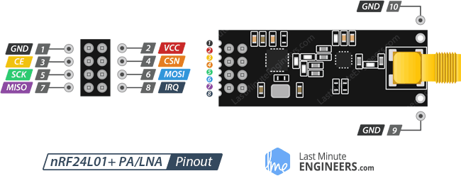
tutorial basico NRF24L01 amb Arduino
Ramon : i no és més fàcil fer-ho directament amb Wifi o Bluetooth ?
Nano NRF24
D12 -> M1
D11 -> M0
D13 -> SCK
D8 -> CS1
D9 -> CE
Vin -> Vcc ; Vin no es de entrada al Nano ? Igual hauria de ser el pin "5 V"
GND -> GND
KY-037 and KY-038
Both these sound sensors are almost the same, the only difference is that KY-037 has a microphone with a higher sensitivity than KY-038.
simply IOT sensors
KY-037 Specifications
This module has
- a CMA-6542PF electret condenser microphone,
- a LM393 differential comparator to control the digital output,
- a 3296W potentiometer to adjust the detection threshold,
- 6 resistors, 2 LEDs and 4 male header pins.
The module features analog and digital outputs.
- operating voltage : 3.3 V ~ 5.5 V
- microphone sensitivity : -42 ±3 db
- current consumption : ~0.5 mA
- board dimensions 15 mm x 36 mm
Arduino modules
sensor de sonido KY-038
KY-038 datasheet
tutorial - tutorial :
- consum ?
- pines de conexion :
- Vcc : +5 v
- D0 : salida digital que actúa a modo de comparador. Si el sonido captado por el micrófono supera un determinado nivel se pone a HIGH.
- A0 : salida analógica que nos da un valor entre 0 y 5 V en función del volumen del sonido.
- Gnd : 0 v
- Además tenemos dos LEDs, uno que nos indica si hay alimentación en el sensor y otro que se ilumina si D0 está a HIGH.
Diferencia amb KY-037 ?
Los sensores de sonido KY-038 y KY-037 son muy similares.
La única diferencia es la sensibilidad que tiene cada uno.
El de mayor sensibilidad es el KY-037.
Comparador : LM393
Programacio A i D,
encendre foco
Adjust the potentiometer for the KY-038 / KY-037 Module
The resistance of the potentiometer is the main influencing variable for the output of the first comparator and therefore for the digital output of the sound sensor module.
Because the status of the digital output is directly visible through LED L2, we will concentrate on LED2 to adjust the potentiometer.
In my opinion, the easiest way to set the resistance of the potentiometer is the following:
- do not make any extra sound
- turn the potentiometer until LED L2 turns on
- turn the potentiometer slowly in the opposite direction so that LED L2 turns off - the digital output D0 is LOW
- tap beside the KY-038 or KY-037 microphone sound sensor module
- LED L2 should turn on by an active sound
diyi0t.com
Conexio entre Arduino "Nano" i KY-037
.--------------------------. .--------------------------.
| | |
| Vin o | | o AO
GND o | | o GND
Rst o | | o +5V
+5V o | | o DO
| |
| .--------------------------.
AO o |
Aref o | Nano KY-037
| 3v3 o | AO AO
| o D12 D13 o | GND GND
| | +5V +5V
.--------------------------. D12 DO
Albert's ESP32 "TTGO"
El 2023.02.09 en Albert em regala un LILYGO "TTGO",
FCC id 2ASYE-T-display v 1.1
amb una bateria "PKCELL LP503035" de 3,7 V i 500 mAh {duració aproximada 3 hores "send to bot"}
Caixa (body.stl) :
instructables
Specs +
specs (8,99 USD) :
- chip ESP32 (procesador de doble núcleo de 240 Mhz)
ESP32 Xtensa dual-core LX6 microprocessor
- serial chip : CH9102F (USB to serial converter)
- SRAM: 520 KB
- memoria flash, QSPI flash: 4 MB
- connectivity : Wi-Fi 802.11 b/g/n, Bluetooth BL V4.2+BLE
- pantalla TFT (IPS ST7789V) de 1,14 pulgadas (240x135) - High Density 260 PPI, 4-Wire SPI interface
display RGB de 1.14 pulgadas de 135 x 240 puntos con un driver ST7789V
- github LilyGo team - with schematic
Quick start
- copy TFT_eSPI to the <C:\Users\Your User Name\Documents\Arduino\libraries> directory
- open Arduino IDE, find TFT_eSPI in the file
the T-Display factory test program is located at TFT_eSPI -> FactoryTest,
you can also use other sample programs provided by TFT_eSPI
- in the Arduino IDE tool options, select the development board ESP32 Dev Module (or "LilyGo T-Display"),
select Disable in the PSRAM option, select 4MB in the Flash Size option.
Other keep the default
- select the corresponding serial port.
- finally, click upload, the right arrow next to the tick
LEDs and switches and Hall sensor
There are 2 LEDs on this board : BLUE (power indicator) and GREEN (wifi indicator).
The GREEN LED can be controlled with GPIO-21.
To turn off the BLUE LED, power the board with Lithium battery interface.
There are 2 buttons on this board : left (from USB-C) button is GPIO-0, right button is GPIO-35
There is a Hall sensor on the board :
>>> import esp32 ; MicroPython
>>> esp32.hall_sensor()
53
Using IDE :
int val = 0;
void setup() {
Serial.begin(9600);
}
void loop() { // put your main code here, to run repeatedly
val = hallRead(); // read hall effect sensor value
Serial.println(val); // print the results to the serial monitor
delay(1000);
}
random nerd tutorials
Some more board details :
quickref :
temperature sensor, clock speed, flash size, ULP, PWM, ADC, webrpl, ...
conexio del display
El display está conectado al ESP32 a través de 6 pines.
Cuatro de ellos están relacionados con la interface SPI:
- MOSI (Entrada de datos al display. Pin 19)
- SCLK (Señal de Clock. Pin 18)
- CS (Habilitación del display. Pin 5)
- DC (Data/Command. Pin 16)
Los otros dos son de control:
- RST (Reset del Display. Pin 23)
- y BL (Encendido del backlight. Pin 4).
acces a la pantalla des Arduino
La pantalla te 240 pixels de ample (width, X) per 135 pixels de alt (height, Y)
Hem de codificar :
#include <TFT_eSPI.h> // manage graphics
#include <SPI.h> // manage SPI port
TFT_eSPI tft = TFT_eSPI();
void setup() { // put your setup code here, to run once
InitSerial() ; //
Serial.println( "*** escriure a pantalla v 1.0 ***" ) ;
tft.init();
tft.fillScreen(TFT_BLACK);
tft.setRotation(3); // [0..3]
} ; // setup()
void loop() { // put your main code here, to run repeatedly
cnt = cnt + 1 ;
delay(3000);
tft.fillScreen(TFT_BLACK);
tft.drawRect(0, 0, tft.width(), tft.height(), TFT_RED);
tft.setTextColor(TFT_GREEN, TFT_BLACK);
tft.setFreeFont(&Orbitron_Light_24);
tft.setCursor(10, 40); // (x, y)
tft.print("loop number ...");
tft.drawLine(10, 60, 230, 60, TFT_BLUE);
tft.setFreeFont(&Orbitron_Light_32);
tft.setCursor(10, 120);
tft.print(cnt);
Serial.print ( cnt ) ;
Serial.println(" +++ serial line example");
} ; // loop()
contingut de <TFT_eSPI.h>
documentacio Arduino ->
repositori github {*****} ;
tft-espi readthedocs
doc TFT ESPI
diferencia
tft.begin()
and "tft.init()" ???
// init() and begin() are equivalent, begin() included for backwards compatibility
Quins valors pot agafar la font ?
master fonts -> "Custom" -> "Orbitron_Light" 24 i 32
m5stack :
tft.setFreeFont(&Orbitron_Light_24);
tft.setFreeFont(&Orbitron_Light_32);
rc = writeText ( "3 - TRE", FreeMonoBold24pt7b ) ; // https://m5stack.lang-ship.com/howto/m5gfx/font/
rc = writeText ( "n - ENE", FreeSansBold9pt7b ) ; // https://m5stack.lang-ship.com/howto/m5gfx/font/
int writeText ( String szText,
const GFXfont szFF ) {
int iRC = 0 ;
tft.fillScreen(TFT_BLACK);
tft.drawRect(0, 0, tft.width(), tft.height(), TFT_RED);
tft.setTextColor(TFT_GREEN, TFT_BLACK);
tft.setFreeFont(&szFF);
tft.setCursor(20, 80);
tft.print(szText);
return iRC ;
} ; // writeText () ;
lets run the TTGO
- verify user is in "dialout" group :
nicolau@mars:~$ cat /etc/group
dialout:x:20:nicolau
otherwise, run "sudo usermod -a -G dialout nicolau"
sebas@minie:~$ sudo usermod -a -G dialout sebas
sebas@minie:~$ cat /etc/group | grep dialout
dialout:x:20:sebas
Please logout() and login() again ...
- connect TTGO to MARS
sebas@minie:~$ dmesg
[ 1829.756559] usb 1-2: new full-speed USB device number 8 using xhci_hcd
[ 1829.902519] usb 1-2: New USB device found, idVendor=1a86, idProduct=55d4, bcdDevice= 4.43
[ 1829.902526] usb 1-2: New USB device strings: Mfr=0, Product=2, SerialNumber=3
[ 1829.902529] usb 1-2: Product: USB Single Serial
[ 1829.902532] usb 1-2: SerialNumber: 5473008093
[ 1829.930371] cdc_acm 1-2:1.0: ttyACM0: USB ACM device
[ 1829.930395] usbcore: registered new interface driver cdc_acm
[ 1829.930397] cdc_acm: USB Abstract Control Model driver for USB modems and ISDN adapters
- identify port (espressif) it uses :
nicolau@mars:~$ ls /dev/ttyA*
0 crw-rw---- 1 nicolau dialout 166, 0 Feb 10 17:11 /dev/ttyACM0
sebas@minie:~$ ls /dev/ttyA*
0 crw-rw---- 1 root dialout 166, 0 Sep 9 17:10 /dev/ttyACM0
The default console baud rate on ESP32 is 115200
- VID: 1A86, PID: 55D4 :
nicolau@mars:~$ lsusb
Bus 003 Device 002: ID 1a86:55d4 QinHeng Electronics
sebas@minie:~$ lsusb
Bus 001 Device 008: ID 1a86:55d4 QinHeng Electronics USB Single Serial
- Install "Arduino IDE" : v2.3.2 using Mint "Software Manager"
- configure Arduino IDE (espressif)
- open Arduino IDE "Preferences"
- add
this URL into
Additional Board Manager URLs field {requires Arduino IDE version >= 1.8}
- in "Boards Manager" install esp32 platform
- in "Tools" -> "Board" select "ESP32 Dev Module"
- start "Arduino IDE" :
- Board: "ESP32 Dev Module"
- Port: "/dev/ttyACM0"
- install TFT_eSPI library :
- Need #include <TFT_eSPI.h> // TFT hardware-specific library"
Use "Library Manager" + TFT_eSPI by Bodmer
Result : {minie}/home/sebas/Arduino/libraries/TFT_eSPI, versio 2.5.43
Bodmer at github
Solucio : TFT_eSPI.h
ALL zip !
- from "Arduino libraries", get TFT_eSPI
Supports TFT displays using drivers (ILI9341 etc) that operate with hardware SPI or 8/16 bit parallel
- put it in directory
"/home/nicolau/sebas/esp32/codi/libraries/TFT_eSPI"
Minie : /home/sebas/dades/esp32/codi_arduino/libraries/TFT_eSPI
- set user configuration in "codi/libraries/TFT_eSPI/User_Setup_Select.h", as
jmaathuis (*** detailed install ***) says
// Only ONE line below should be uncommented to define your setup.
// *** SAG 20230213 (1/3)
// #include <User_Setup.h> // Default setup is root library folder
// *** SAG 20230213 (2/3)
// #include <User_Setups/Setup136_LilyGo_TTV.h> // Setup file for ESP32 and Lilygo TTV ST7789 SPI bus TFT 135x240
// *** SAG 20230213 (3/3) *** aquesta funciona !
#include TTGO_T_Display.h // from
ubcenvcom
#include <User_Setups/TTGO_T_Display.h> // Mint 20240808
- learn how to use TFT_eSPI library on TTGO t-display board
Hard resetting via RTS pin ... {not an error}
- run factory test :
FactoryTest.ino,
bmp.h,
Button2.h
details
- run some samples from "File -> Examples -> from custom libraries -> TFT_eSPI"
- run
Colour_Test.ino,
by bodmer
- test botons a pantalla
Sorpresa :
Button 2 Pressed!
Button 2 Pressed!
Button Guru Meditation Error: Core 1 panic'ed (Interrupt wdt timeout on CPU1).
Core 1 register dump:
PC : 0x4008b11d PS : 0x00060f35 A0 : 0x80089948 A1 : 0x3ffbf6fc
A2 : 0x3ffb88ec A3 : 0x3ffb81a0 A4 : 0x00000004 A5 : 0x00060f23
A6 : 0xb33fffff A7 : 0xb33fffff A8 : 0x3ffb81a0 A9 : 0x3ffb81a0
A10 : 0x00000018 A11 : 0x00000018 A12 : 0xb33fffff A13 : 0x3f40b530
A14 : 0xb33fffff A15 : 0xb33fffff SAR : 0x00000020 EXCCAUSE: 0x00000006
EXCVADDR: 0x00000000 LBEG : 0x40086655 LEND : 0x40086665 LCOUNT : 0xfffffffb
Core 1 was running in ISR context:
EPC1 : 0x400de66f EPC2 : 0x00000000 EPC3 : 0x00000000 EPC4 : 0x00000000
Backtrace: 0x4008b11a:0x3ffbf6fc |<-CORRUPTED
Core 0 register dump:
PC : 0x40086984 PS : 0x00060035 A0 : 0x80089543 A1 : 0x3ffbf07c
A2 : 0x3ffbdd64 A3
Solucio : User_Setup_Select.h ha de tenir "#include TTGO_T_Display.h"
- tambe funciona Colour_Test.ino
TTGO - colour test
- connect the TTGO to minie
- use "dmesg" to verify it uses "/dev/ttyACM0"
- select "board := ESP32-WROOM-DA Module" and "port := /dev/ttyACM0"
- upload and run code from "/home/sebas/Arduino/esp32-ttgo/color_test" (not "colour")
TTGO - display BTC
- source : projecthub
- create a CoinAPI account and request a free Market Data API key [/] - 100 API calls per day
- get (using "Tools -> Manage libraries") ArduinoJson.h (v 7.2.1)
... and Adafruit_GFX.h (v 1.11.11) and Adafruit_ST7789.h (v 1.10.4)
See "/home/sebas/Arduino/esp32-ttgo/btc" - connects to wifi,
sends http.get(), deserializes received JSON and displays it on screen
Our code is on
GitHub !!!
Main lines are :
void displayBitcoinPrice() {
if (WiFi.status() == WL_CONNECTED) {
HTTPClient http;
http.begin(api_url); // const char* api_url = "https://rest.coinapi.io/v1/exchangerate/BTC/USD";
http.addHeader("X-CoinAPI-Key", api_key);
int httpCode = http.GET(); // make the request
Serial.print (">>> http.GET rc is ... ");
Serial.println(httpCode);
if (httpCode > 0) {
String payload = http.getString();
Serial.print (">>> payload is ... ");
Serial.println(payload);
DynamicJsonDocument doc(1024) ;
deserializeJson(doc, payload);
float price = doc["rate"];
String date = doc["time"];
String formatted_date = formatTime(date);
Serial.print (">>> timestamp is ... {");
Serial.print (formatted_date);
Serial.print ("}, price is ... ");
Serial.println(price);
// Display the price on the OLED
tft.fillScreen(TFT_BLACK);
tft.drawRect(0, 0, tft.width(), tft.height(), TFT_RED);
tft.setTextColor(TFT_GREEN, TFT_BLACK);
tft.setFreeFont(&Orbitron_Light_24);
tft.setCursor(10, 30);
tft.print("Bitcoin Price");
tft.setCursor(10, 60);
tft.print("USD ");
tft.setCursor(80, 60);
tft.print(price, 2);
tft.setTextColor(TFT_BLUE, TFT_BLACK);
tft.setFreeFont(&Orbitron_Light_24);
tft.setCursor(10, 115);
tft.print(formatted_date);
} else {
Serial.println("--- Error on HTTP request");
} // if httpCode
http.end(); // End the request
} // if CONNECTED
} ; // displayBitcoinPrice()
TTGO "read BTC" code in GITHUB
gitlab tutorials -> we go to GITHUB
- github homepage ->
BTC code
- install git using "Software Manager" at minie :
sebas@minie:~$ git version
git version 2.34.1
- create ".git" ; initialize empty git repository at /home/sebas/Arduino/esp32-ttgo/btc
sebas@minie:~/Arduino/esp32-ttgo/btc$ git init
Hint: Using 'master' as the name for the initial branch.
hint: 'development'. The just-created branch can be renamed via this command:
hint: git branch -m <name>
- configure user name and email :
sebas@minie:~/Arduino/esp32-ttgo/btc$ git config --global user.name "Ramonet"
sebas@minie:~/Arduino/esp32-ttgo/btc$ git config --global user.name
Ramonet
sebas@minie:~/Arduino/esp32-ttgo/btc$ git config --global user.email "campdefabes@gmail.com"
sebas@minie:~/Arduino/esp32-ttgo/btc$ git config --global user.email
campdefabes@gmail.com
See configured values by
sebas@minie:~/Arduino/esp32-ttgo/btc$ git config --list
user.email=campdefabes@gmail.com
user.name=Ramonet
core.repositoryformatversion=0
core.filemode=true
core.bare=false
core.logallrefupdates=true
remote.origin.url=git@github.com:ramonetnet/btc.git
remote.origin.fetch=+refs/heads/*:refs/remotes/origin/*
branch.main.remote=origin
branch.main.merge=refs/heads/main
- add some files :
sebas@minie:~/Arduino/esp32-ttgo/btc$ git add README.md
sebas@minie:~/Arduino/esp32-ttgo/btc$ git add btc.ino
sebas@minie:~/Arduino/esp32-ttgo/btc$ git add .gitignore
... where .gitignore has
.git # no cal : the .git folder is automatically ignored
# old files
oldies
# claus
credentials.h
# ajuda
welcome.sag
- do initial commit (local)
sebas@minie:~/Arduino/esp32-ttgo/btc$ git commit -am "1.0 tot el contingut inicial"
[master (root-commit) 003bdef] 1.0 tot el contingut inicial
3 files changed, 213 insertions(+)
create mode 100644 .gitignore
create mode 100644 README.md
create mode 100644 btc.ino
- create new repository in github and follow instructions :
sebas@minie:~/Arduino/esp32-ttgo/btc$ git branch -M main
sebas@minie:~/Arduino/esp32-ttgo/btc$ git remote add origin git@github.com:ramonetnet/btc.git
- push local code to GitHub :
sebas@minie:~/Arduino/esp32-ttgo/btc$ git push -u origin main
git@github.com: Permission denied (publickey).
fatal: Could not read from remote repository.
Please make sure you have the correct access rights and the repository exists.
- verify you are connecting to the right domain :
sebas@minie:~/Arduino/esp32-ttgo/btc$ ssh -vT git@github.com
git@github.com: Permission denied (publickey).
- verify that you have a private key generated and loaded into SSH :
sebas@minie:~/Arduino/esp32-ttgo/btc$ ssh-add -l -E sha256
The agent has no identities.
We need to generate a new SSH key and associate it with GitHub :
sebas@minie:~/Arduino/esp32-ttgo/btc$ ssh-keygen -t ed25519 -C "campdefabes@gmail.com"
Generating public/private ed25519 key pair.
Enter file in which to save the key (/home/sebas/.ssh/id_ed25519):
Enter passphrase (empty for no passphrase): *no se pas*
Enter same passphrase again:
Your identification has been saved in /home/sebas/.ssh/id_ed25519
Your public key has been saved in /home/sebas/.ssh/id_ed25519.pub
The key fingerprint is:
SHA256:cpoY/C76RC7xP0h4hrroQ045DSz/+0jcwCyxVt2MfZ4 campdefabes@gmail.com
The key's randomart image is:
+--[ED25519 256]--+
| |
| . = |
|. . . o + . |
|.o B o . |
|..OoB . S E |
| *+O+* = |
|+.o=B.= |
|oo +++. |
|+ooo+++. |
+----[SHA256]-----+
sebas@minie:~/Arduino/esp32-ttgo/btc$
send your SSH private key to the ssh-agent :
sebas@minie:~/Arduino/esp32-ttgo/btc$ ssh-add ~/.ssh/id_ed25519
Enter passphrase for /home/sebas/.ssh/id_ed25519:
Identity added: /home/sebas/.ssh/id_ed25519 (campdefabes@gmail.com)
add the SSH public key to your account on GitHub -
url
sebas@minie:~/Arduino/esp32-ttgo/btc$ cat ~/.ssh/id_ed25519.pub
... copy the display to clipboard
... on GitHub page, under your profile foto, open Settings
... in the "Access" section of the sidebar, click "SSH and GPG keys"
... click "New SSH key"
... set any title, select type of key (authentication)
... in the "Key" field, paste your public key -
verify we have access to GitHub :
sebas@minie:~/Arduino/esp32-ttgo/btc$ ssh -vT git@github.com
OpenSSH_8.9p1 Ubuntu-3ubuntu0.10, OpenSSL 3.0.2 15 Mar 2022
debug1: Reading configuration data /etc/ssh/ssh_config
...
Hi ramonetnet! You've successfully authenticated, but GitHub does not provide shell access.
- again, push local code to GitHub :
sebas@minie:~/Arduino/esp32-ttgo/btc$ git push -u origin main
Enumerating objects: 5, done.
Counting objects: 100% (5/5), done.
Delta compression using up to 16 threads
Compressing objects: 100% (4/4), done.
Writing objects: 100% (5/5), 2.32 KiB | 2.32 MiB/s, done.
Total 5 (delta 0), reused 0 (delta 0), pack-reused 0
To github.com:ramonetnet/btc.git
* [new branch] main -> main
Branch 'main' set up to track remote branch 'main' from 'origin'.
TTGO - send to Telegram bot
We shall be using
Universal Telegram bot library.
This library provides an interface for Telegram Bot API.
Get it: Universal-Arduino-Telegram-Bot-master.zip from
here + "Code" + "Download Zip"
... and the downloaded code can be included as a new library into the IDE selecting the menu:
Sketch / include Library / Add .Zip library
You also have to install the ArduinoJson library
sebas@minie:~/Arduino/esp32-ttgo/send_to_bot$ cat send_to_bot.ino
#include <WiFiClientSecure.h> //
#include <UniversalTelegramBot.h> //
https://github.com/witnessmenow/Universal-Arduino-Telegram-Bot
#include <credentials.h>
const char* BOTtoken = STA_BOT_token ;
const char* CHAT_ID = STA_CHAT_ID ;
WiFiClientSecure secured_client ; //
UniversalTelegramBot bot( BOTtoken, secured_client ) ; // create object
void TG_msg_2_bot ( const String & szMsg ) {
szOut = String(">>> ") + String(szMsg) + String(" <<<") ;
bot.sendMessage( CHAT_ID, szOut );
} ; // TG_msg_2_bot ( String )
void connectToWiFi() {
WiFi.mode( WIFI_STA ) ; // ?
WiFi.begin(ssid, password) ;
secured_client.setCACert( TELEGRAM_CERTIFICATE_ROOT ) ; //
while (WiFi.status() != WL_CONNECTED) {
delay(1000);
msg_2_screen("... wait 1 sg ...");
}
szOut = "+++ connected to Wi-Fi ... IP address: " + WiFi.localIP().toString() ;
msg_2_screen( szOut ) ;
} ; // connectToWiFi() ;
void setup() {
InitSerial() ; // Initialize serial communication
Serial.println( "*** SETUP() send to bot.ino v 1.1.b ***" ) ;
connectToWiFi() ; // connect to wifi
} ; // setup()
void loop() {
cnt = cnt + 1 ;
szOut = String( cnt ) + " >>> IP : " + WiFi.localIP().toString() ;
TG_msg_2_bot( szOut ) ;
delay(waiting_time);
} ; // loop()
electronic wings
Here is another project sendin temperature on request :
random nerd tutorials
TTGO - implement a Telegram bot
Pending ...
control outputs using Telegram :
random nerd tutorials
TTGO - NTP client - get time using NTP
NTP :
ethernet shield,
UDP,
NTP client code
const char* ntpServer = "pool.ntp.org";
const char *ntpServer1 = "pool.ntp.org";
const char *ntpServer2 = "time.nist.gov";
void setup() {
Serial.begin(115200);
delay(2000);
Serial.println("\n Setup-Start \n");
PrintFileNameDateTime();
connectToWifi();
synchroniseWith_NTP_Time();
} ; // setup()
const long gmtOffset_sec = 0; // 3600 - https://github.com/espressif/arduino-esp32/blob/master/libraries/ESP32/examples/Time/SimpleTime/SimpleTime.ino
const int daylightOffset_sec = 7200; // 3600
const char *time_zone = "CET-1CEST,M3.5.0,M10.5.0/3"; // TimeZone rule for Europe/Rome including daylight adjustment rules (optional)
// * a list of rules for your zone could be obtained from https://github.com/esp8266/Arduino/blob/master/cores/esp8266/TZ.h
void synchroniseWith_NTP_Time() {
Serial.print("configTime uses ntpServer ");
Serial.println(ntpServer);
// configTime(gmtOffset_sec, daylightOffset_sec, ntpServer); //
configTzTime(time_zone, ntpServer1, ntpServer2);
Serial.print("synchronising time");
while (myTimeInfo.tm_year + 1900 < 2000 ) {
time(&now); // read the current time
localtime_r(&now, &myTimeInfo);
BlinkHeartBeatLED(OnBoard_LED, 100);
delay(100);
Serial.print(".");
}
Serial.print("\n time synchronsized \n");
showTime();
} ; // synchroniseWith_NTP_Time()
void showTime() {
time(&now); // read the current time
localtime_r(&now, &myTimeInfo); // update the structure tm with the current time
updateMyTimeVars();
Serial.print("year:"); Serial.print(iYear);
Serial.print(" month:"); if (iMonth < 10) { Serial.print("0"); } ; Serial.print(iMonth);
Serial.print(" day:"); if (iDay < 10) { Serial.print("0"); } ; Serial.print(iDay); // day of month
Serial.print(" hour:"); if (iHour < 10) { Serial.print("0"); } ; Serial.print(iHour); // hours since midnight 0-23
Serial.print(" min:"); if (iMinute < 10) { Serial.print("0"); } ; Serial.print(iMinute); // minutes after the hour 0-59
Serial.print(" sec:"); if (iSecond < 10) { Serial.print("0"); } ; Serial.print(iSecond); // seconds after the minute 0-59
Serial.print(" day "); Serial.print(dayOfWeek[iDayIndex]);
Serial.println();
} ; // showTime()
large code example,
short {see TZ}
micropython on ESP32
micropython
homepage,
documentation as
libraries ,
emulador,
wikipedia (en)
Arduino.cc -> micro python
Hi ha dos arxius clau al micropython :
- boot.py executa una sola vegada (configures ports, etc)
- main.py en bucle infinit
REPL starts after both boot.py and main.py have finished - "read–eval–print loop"
An endless loop in boot.py or main.py prevents REPL.
- get micropython ".bin" file :
- mycropython downloads esp32
- vendor=LILYGO
- LILYGO_TTGO_LORA32
- LILYGO_TTGO_LORA32-20220618-v1.19.1.bin {v1.19.1, MARS/sebas/esp32}
Looks this is the wrong one ("import st7789" fails) - en Albert em donarà el ".bin" bo :
Russ Hughes
- load it onto your ESP32 device :
- upgrade pip : "python3 -m pip install --upgrade pip"
- install esptool,
"a Python-based, open-source, platform-independent utility to communicate with the ROM bootloader in Espressif chips"
nicolau@mars:~$ python3 -m pip install esptool
"Python.h" not found : install "python3-dev"
I have python 3.7.5, so I use
nicolau@mars:~$ sudo apt install libpython3.7-dev
nicolau@mars:~$ which esptool.py
/home/nicolau/.local/bin/esptool.py
- install
nicolau@mars:~$ python3 -m pip install adafruit-ampy
Defaulting to user installation because normal site-packages is not writeable
Collecting adafruit-ampy
Downloading adafruit_ampy-1.1.0-py2.py3-none-any.whl (16 kB)
Requirement already satisfied: pyserial in /home/nicolau/.local/lib/python3.7/site-packages (from adafruit-ampy) (3.5)
Requirement already satisfied: click in /usr/lib/python3/dist-packages (from adafruit-ampy) (6.7)
Collecting python-dotenv
Downloading python_dotenv-0.21.1-py3-none-any.whl (19 kB)
Installing collected packages: python-dotenv, adafruit-ampy
Successfully installed adafruit-ampy-1.1.0 python-dotenv-0.21.1
nicolau@mars:~$ which ampy
/home/nicolau/.local/bin/ampy
- create "makefile" :
nicolau@mars:~/sebas/esp32/micropython$ cat makefile
# Makefile
# Albert 2023-02-17
.PHONY = help check-deps install-deps flash flash put get
BAUDRATE=115200
TTY=/dev/ttyACM0
all: help
help:
@echo "Makefile - automate ESP boards"
@echo
@echo " $$make check-deps / install-deps"
@echo
@echo " $$make flash FIRMWARE=xxx"
@echo " $$make id - use in case of blocked ESP32"
@echo " $$make prompt"
@echo " $$make put FILE=xxx"
check-deps:
which esptool.py
which ampy
install-deps:
sudo apt-get update
pip3 install esptool
pip3 install adafruit-ampy
sudo usermod -a -G dialout $(shell whoami)
flash:
esptool.py --chip esp32 --port $(TTY) erase_flash
ls -l $(FIRMWARE)
esptool.py --chip esp32 --port $(TTY) --baud 460800 write_flash -z 0x1000 $(FIRMWARE)
id:
esptool.py --chip esp32 --port $(TTY) --baud 460800 flash_id
prompt:
# sudo picocom $(TTY) -b$(BAUDRATE)
minicom -b $(BAUDRATE) -D $(TTY)
put:
ampy -p $(TTY) put $(FILE)
- erase
nicolau@mars:~$ esptool.py --port /dev/ttyACM0 erase_flash
esptool.py v4.5
Serial port /dev/ttyACM0
Connecting....
Detecting chip type... Unsupported detection protocol, switching and trying again...
Connecting.......
Detecting chip type... ESP32
Chip is ESP32-D0WDQ6-V3 (revision v3.0)
Features: WiFi, BT, Dual Core, 240MHz, VRef calibration in efuse, Coding Scheme None
Crystal is 40MHz
MAC: 94:b5:55:c7:05:bc
Uploading stub...
Running stub...
Stub running...
Erasing flash (this may take a while)...
Chip erase completed successfully in 6.6s
Hard resetting via RTS pin...
- read chip model :
nicolau@mars:~$ esptool.py --chip esp32 --port /dev/ttyACM0 --baud 460800 flash_id
esptool.py v4.5
Serial port /dev/ttyACM0
Connecting....
Chip is ESP32-D0WDQ6-V3 (revision v3.0)
Features: WiFi, BT, Dual Core, 240MHz, VRef calibration in efuse, Coding Scheme None
Crystal is 40MHz
MAC: 94:b5:55:c7:05:bc
Uploading stub...
Running stub...
Stub running...
Changing baud rate to 460800
Changed.
Manufacturer: 68
Device: 4016
Detected flash size: 4MB
Hard resetting via RTS pin...
- install micropython
nicolau@mars:~$ esptool.py --chip esp32 --port /dev/ttyACM0 --baud 460800 write_flash -z 0x1000 /home/nicolau/sebas/esp32/micropython/LILYGO_TTGO_LORA32-20220618-v1.19.1.bin
esptool.py v4.5
Serial port /dev/ttyACM0
Connecting.......
Chip is ESP32-D0WDQ6-V3 (revision v3.0)
Features: WiFi, BT, Dual Core, 240MHz, VRef calibration in efuse, Coding Scheme None
Crystal is 40MHz
MAC: 94:b5:55:c7:05:bc
Uploading stub...
Running stub...
Stub running...
Changing baud rate to 460800
Changed.
Configuring flash size...
Flash will be erased from 0x00001000 to 0x0017dfff...
Compressed 1558176 bytes to 1027088...
Wrote 1558176 bytes (1027088 compressed) at 0x00001000 in 23.2 seconds (effective 536.2 kbit/s)...
Hash of data verified.
Leaving...
Hard resetting via RTS pin...
- verify ".bin"
esptool.py --chip esp32 --port /dev/ttyACM0 --baud 460800 verify_flash --diff yes 0x40000 -z 0x1000 LILYGO_TTGO_LORA32-20220618-v1.19.1.bin
- hard reset message :
>>> ets Jul 29 2019 12:21:46
rst:0x1 (POWERON_RESET),boot:0x13 (SPI_FAST_FLASH_BOOT)
configsip: 0, SPIWP:0xee
clk_drv:0x00,q_drv:0x00,d_drv:0x00,cs0_drv:0x00,hd_drv:0x00,wp_drv:0x00
mode:DIO, clock div:2
load:0x3fff0030,len:4540
ho 0 tail 12 room 4
load:0x40078000,len:12344
ho 0 tail 12 room 4
load:0x40080400,len:4124
entry 0x40080680
MicroPython v1.19.1 on 2022-06-18; LILYGO TTGO LoRa32 with ESP32
Type "help()" for more information.
>>>
- soft reset message :
>>> {<CTRL> + "D"}
MPY: soft reboot
MicroPython v1.19.1-738-gb042fd512-dirty on 2022-12-09; TTGO T-Display with ESP32
Type "help()" for more information.
- access
nicolau@mars:~$ minicom -b 115200 -D /dev/ttyACM0
>>> CTRL+"D"
MPY: soft reboot
MicroPython v1.19.1 on 2022-06-18; LILYGO TTGO LoRa32 with ESP32
Type "help()" for more information.
>>> help()
Welcome to MicroPython on the ESP32!
For generic online docs please visit http://docs.micropython.org/
For access to the hardware use the 'machine' module:
import machine
pin12 = machine.Pin(12, machine.Pin.OUT)
pin12.value(1)
pin13 = machine.Pin(13, machine.Pin.IN, machine.Pin.PULL_UP)
print(pin13.value())
i2c = machine.I2C(scl=machine.Pin(21), sda=machine.Pin(22))
i2c.scan()
i2c.writeto(addr, b'1234')
i2c.readfrom(addr, 4)
Basic WiFi configuration:
import network
sta_if = network.WLAN(network.STA_IF); sta_if.active(True)
sta_if.scan() # scan for available access points
sta_if.connect("<AP_name>", "<password>") # Connect to an AP
sta_if.isconnected() # check for successful connection
Control commands:
CTRL-A -- on a blank line, enter raw REPL mode
CTRL-B -- on a blank line, enter normal REPL mode
CTRL-C -- interrupt a running program
CTRL-D -- on a blank line, do a soft reset of the board
CTRL-E -- on a blank line, enter paste mode
For further help on a specific object, type help(obj)
For a list of available modules, type help('modules')
>>>
- read quick ref
- see modules we have :
>>> help("modules")
NotoSansMono_32 greekp symbol ure
NotoSans_32 greeks uarray urequests
NotoSerif_32 inconsolata_16 uasyncio/__init__ uselect
__main__ inconsolata_32 uasyncio/core usocket
_boot inisetup uasyncio/event ussl
_onewire italicc uasyncio/funcs ustruct
_thread italiccs uasyncio/lock usys
_uasyncio marker uasyncio/stream utime
_webrepl math ubinascii utimeq
apa106 meteo ubluetooth uwebsocket
axp202c micropython ucollections uzlib
btree mip ucryptolib vga1_16x16
builtins music uctypes vga1_16x32
cmath neopixel uerrno vga1_8x16
df network uhashlib vga1_8x8
dht ntptime uheapq vga1_bold_16x16
ds18x20 onewire uio vga1_bold_16x32
esp romanc ujson vga2_16x16
esp32 romancs umachine vga2_8x16
flashbdev romand umqtt/robust vga2_8x8
framebuf romanp umqtt/simple vga2_bold_16x16
fs romans uos vga2_bold_16x32
gc scriptc uplatform webrepl
greekc scripts upysh webrepl_setup
greekcs st7789 urandom
Plus any modules on the filesystem
- "machine" module details :
>>> import machine
>>> dir(machine)
['__class__', '__name__', 'ADC', 'ADCBlock', 'DAC', 'DEEPSLEEP', 'DEEPSLEEP_RESET',
'EXT0_WAKE', 'EXT1_WAKE', 'HARD_RESET', 'I2C', 'I2S', 'PIN_WAKE', 'PWM', 'PWRON_RESET',
'Pin', 'RTC', 'SDCard', 'SLEEP', 'SOFT_RESET', 'SPI', 'Signal', 'SoftI2C', 'SoftSPI',
'TIMER_WAKE', 'TOUCHPAD_WAKE', 'Timer', 'TouchPad', 'UART', 'ULP_WAKE', 'WDT', 'WDT_RESET',
'bitstream', 'deepsleep', 'disable_irq', 'enable_irq', 'freq', 'idle', 'lightsleep', 'mem16', 'mem32', ...]
>>>
>>> help(machine)
object <module 'umachine'> is of type module
__name__ -- umachine
mem8 -- <8-bit memory>
mem16 -- <16-bit memory>
mem32 -- <32-bit memory>
freq -- <function>
reset -- <function>
soft_reset -- <function>
unique_id -- <function>
sleep -- <function>
lightsleep -- <function>
deepsleep -- <function>
idle -- <function>
disable_irq -- <function>
enable_irq -- <function>
bitstream -- <function>
time_pulse_us -- <function>
Timer -- <class 'Timer'>
WDT -- <class 'WDT'>
SDCard -- <class 'SDCard'>
SLEEP -- 2
DEEPSLEEP -- 4
Pin -- <class 'Pin'>
Signal -- <class 'Signal'>
TouchPad -- <class 'TouchPad'>
ADC -- <class 'ADC'>
ADCBlock -- <class 'ADCBlock'>
DAC -- <class 'DAC'>
I2C -- <class 'I2C'>
SoftI2C -- <class 'SoftI2C'>
I2S -- <class 'I2S'>
PWM -- <class 'PWM'>
RTC -- <class 'RTC'>
SPI -- <class 'SPI'>
SoftSPI -- <class 'SoftSPI'>
UART -- <class 'UART'>
reset_cause -- <function>
HARD_RESET -- 2
PWRON_RESET -- 1
WDT_RESET -- 3
DEEPSLEEP_RESET -- 4
SOFT_RESET -- 5
wake_reason -- <function>
PIN_WAKE -- 2
EXT0_WAKE -- 2
EXT1_WAKE -- 3
TIMER_WAKE -- 4
TOUCHPAD_WAKE -- 5
ULP_WAKE -- 6
>>>
>>> help(machine.Pin)
object <class 'Pin'> is of type type
init -- <function>
value -- <function>
off -- <function>
on -- <function>
irq -- <function>
IN -- 1
OUT -- 3
OPEN_DRAIN -- 7
PULL_UP -- 2
PULL_DOWN -- 1
IRQ_RISING -- 1
IRQ_FALLING -- 2
WAKE_LOW -- 4
WAKE_HIGH -- 5
DRIVE_0 -- 0
DRIVE_1 -- 1
DRIVE_2 -- 2
DRIVE_3 -- 3
show display model :
>>> import machine
>>> i2c = machine.I2C(scl=machine.Pin(21), sda=machine.Pin(22))
Warning: I2C(-1, ...) is deprecated, use SoftI2C(...) instead
>>> i2c.scan()
[]
>>> import machine
>>> i2c = machine.I2C(scl=machine.Pin(19), sda=machine.Pin(23))
>>> i2c.scan()
[]
>>> import machine
>>> si2c = machine.SoftI2C(scl=machine.Pin(18), sda=machine.Pin(19))
>>> si2c.scan()
[]
If you do a I2C scan, if the address is 0x3C, it is SSD1306.
If you get 0x78 or 0x7A, then you have a SH-1106 display.
stackoverflow
- try REPL, "read–eval–print loop" :
for i in range(1000000):
print(i) // mind start the line with "TAB"
After you write print(i), press RETURN, press BACKSPACE and press RETURN again to execute the code.
- atencio al modul "webrepl" : esp32.com
- unfortunatelly, this image has no "requests" or "urequests", neither "curl" :
MPY: soft reboot
MicroPython v1.19.1 on 2022-06-18; LILYGO TTGO LoRa32 with ESP32
Type "help()" for more information.
>>> import urequests
Traceback (most recent call last):
File "<stdin>", line 1, in <module>
ImportError: no module named 'urequests'
>>> import curl
Traceback (most recent call last):
File "<stdin>", line 1, in <module>
ImportError: no module named 'curl'
- try russ_hughes ".bin" file :
- russ hughes homepage,
from profe Tolocka
- got "st7789_mpy-master.zip"
st7789 ->
firmware ->
T-display-ESP32
- disconnect minicom !
- make flash FIRMWARE="/home/nicolau/sebas/esp32/micropython/russ_hughes/st7789_mpy-master/firmware/T-DISPLAY-ESP32/firmware.bin"
Saved at "mars\st7789_mpy-master.zip"
$ esptool.py --chip esp32 --port /dev/ttyACM0 erase_flash
esptool.py v4.5
Serial port /dev/ttyACM0
Connecting....
Chip is ESP32-D0WDQ6-V3 (revision v3.0)
Features: WiFi, BT, Dual Core, 240MHz, VRef calibration in efuse, Coding Scheme None
Crystal is 40MHz
MAC: 94:b5:55:c7:05:bc
Uploading stub...
Running stub...
Stub running...
Erasing flash (this may take a while)...
Chip erase completed successfully in 3.8s
Hard resetting via RTS pin...
ls -l /home/nicolau/sebas/esp32/micropython/russ_hughes/st7789_mpy-master/firmware/T-DISPLAY-ESP32/firmware.bin
-rw-rw-r-- 1 nicolau nicolau 1788416 Jan 14 05:45 /home/nicolau/sebas/esp32/micropython/russ_hughes/st7789_mpy-master/firmware/T-DISPLAY-ESP32/firmware.bin
esptool.py --chip esp32 --port /dev/ttyACM0 --baud 460800 write_flash -z 0x1000 /home/nicolau/sebas/esp32/micropython/russ_hughes/st7789_mpy-master/firmware/T-DISPLAY-ESP32/firmware.bin
esptool.py v4.5
Serial port /dev/ttyACM0
Connecting......
Chip is ESP32-D0WDQ6-V3 (revision v3.0)
Features: WiFi, BT, Dual Core, 240MHz, VRef calibration in efuse, Coding Scheme None
Crystal is 40MHz
MAC: 94:b5:55:c7:05:bc
Uploading stub...
Running stub...
Stub running...
Changing baud rate to 460800
Changed.
Configuring flash size...
Flash will be erased from 0x00001000 to 0x001b5fff...
Compressed 1788416 bytes to 1096932...
Wrote 1788416 bytes (1096932 compressed) at 0x00001000 in 24.8 seconds (effective 576.2 kbit/s)...
Hash of data verified.
Leaving...
Hard resetting via RTS pin...
- now a hard (or soft) reset produces those messages to minicom :
>>> ets Jul 29 2019 12:21:46
rst:0x1 (POWERON_RESET),boot:0x13 (SPI_FAST_FLASH_BOOT)
configsip: 0, SPIWP:0xee
clk_drv:0x00,q_drv:0x00,d_drv:0x00,cs0_drv:0x00,hd_drv:0x00,wp_drv:0x00
mode:DIO, clock div:2
load:0x3fff0030,len:5392
load:0x40078000,len:14328
load:0x40080400,len:3456
entry 0x40080638
MicroPython v1.19.1-738-gb042fd512-dirty on 2022-12-09; TTGO T-Display with ESP32
Type "help()" for more information.
>>>
micropython parts
RTC, real time clock
See RTC is installed :
nicolau@mars:~$ ls -l /dev | grep rtc
0 lrwxrwxrwx 1 root root 4 Feb 28 17:00 rtc -> rtc0
0 crw------- 1 root root 249, 0 Feb 28 17:00 rtc0
RTC.datetime([datetimetuple]) - get or set the date and time of the RTC.
With no arguments, this method returns an 8-tuple with the current date and time.
With 1 argument (being an 8-tuple) it sets the date and time.
The 8-tuple has the following format:
(year, month, day, weekday, hours, minutes, seconds, subseconds)
docs micropython
Now sync to NTP :
import time
import ntptime #
ntptime.py by Peter Hinch
try:
print(">>> query NTP")
print("+++ Local time before synchronization [%s]." % str(time.localtime())) # display local time
ntptime.settime() # query time from an NTP server
print("+++ Local time after synchronization [%s]." % str(time.localtime())) # display local time
except:
print("--- Error syncing time")
Setting RTC From Internet?
Display RTC components :
# RTC().datetime() format :
print ("Fecha: {:02d}/{:02d}/{}".format( RTC().datetime()[2], # Fecha: 28/02/2023
RTC().datetime()[1],
RTC().datetime()[0]) )
print ("Hora: {:02d}:{:02d}:{:02d}".format( RTC().datetime()[4], # Hora: 18:37:38
RTC().datetime()[5],
RTC().datetime()[6]) )
Accedint-ne varios :
>>> from machine import RTC
>>> print(RTC().datetime())
(2023, 3, 2, 3, 13, 7, 23, 393827)
>>> print(RTC().datetime()[4:7]) # hh:mm:ss
(13, 7, 36)
>>> print(RTC().datetime()[4:6]) # hh:mm
(13, 8)
>>> print(RTC().datetime()[4:5])
(13,)
>>> print(RTC().datetime()[4:4])
()
>>> print(RTC().datetime()[4:8]) # hh:mm:ss:uu
(13, 9, 8, 363956)
More interesting is
(iYear, iMonth, iDmday, iWeekday, iHour, iMinute, iSecond, iMilisecond) = RTC().datetime()
print ( "### h {:02d}-m {:02d}-s {:02d}-ms {}".format ( iHour, iMinute, iSecond, iMilisecond ) )
RTC().datetime() format :
>>> from machine import RTC
>>> (iYear, iMonth, iDmday, iWeekday, iHour, iMinute, iSecond, iMilisecond) = RTC().datetime()
>>> print( type(iYear))
>>> <class 'int'>
garbage collector
A garbage collector is a form of automatic memory management.
This is a way to reclaim memory occupied by objects that are no longer in used by the program.
This is useful to save space in the flash memory.
>>> import gc
>>> gc.collect()
>>> print('Free RAM:', gc.mem_free())
micropython programs
Lets run some python code in the LILYGO ESP32
display files in directory
>>> import os
>>> os.listdir()
['boot.py', 'random_screen.py']
display file contents
>>> with open('boot.py', 'r') as f: # or 'main.py'
... print(f.read())
... <backspace> + "Enter"
# This file is executed on every boot (including wake-boot from deepsleep)
#import esp
#esp.osdebug(None)
#import webrepl
#webrepl.start()
hello world
Aixo sustirà a la consola ...
print("*** hello world ***")
for i in range(1000000):
print(i)
exit(0)
When I try
nicolau@mars:~/sebas/esp32/micropython$ make put FILE="./hello_world/hello_world.py"
ampy -p /dev/ttyACM0 put ./hello_world/hello_world.py
... on LILYGO I see
>>>
raw REPL; CTRL-B to exit
Solucio : el minicom ha de estar tancat per fer un "put()"
llegir botons
#
from machine import Pin
from time import sleep
led = Pin(21, Pin.OUT) # the GREEN LED can be controlled with GPIO-21
boto_left = Pin(0, Pin.IN) # GPIO-0
boto_right = Pin(35, Pin.IN) # GPIO-35
valor = 0
while True:
qboto_left = boto_left.value()
qboto_right = boto_right.value()
if ( valor == 0 ):
valor = 1
else:
valor = 0
print('>>> valor (%i), bL(%i), bR(%i)' % (valor, qboto_left, qboto_right) )
led.value( valor ) # de fet no veig cap LED verd a la placa
sleep(1) #
random points on display
El origen del sistema de coordenadas se sitúa en el ángulo superior izquierdo de la pantalla.
El valor de X va de 0 a 134 y el de Y de 0 a 239.
from machine import Pin, SPI
import st7789
from time import sleep_ms
from random import randint
spi=SPI(1, baudrate=30000000, polarity=1, phase=1, sck=Pin(18), mosi=Pin(19))
display=st7789.ST7789(
spi,
135,
240,
reset=Pin(23, Pin.OUT),
cs=Pin(5, Pin.OUT),
dc=Pin(16, Pin.OUT),
backlight=Pin(4, Pin.OUT),
rotation=0) # 0 = none, 1 = 90º, 2 = 180º, 3 = 270º
display.init ()
display.rotation(3)
display.offset(40,53)
color_dibujo = st7789.WHITE
color_fondo = st7789.BLACK
while (True):
posx=randint(0,135)
posy=randint(0,240)
display.pixel(posx,posy,st7789.color565(randint (0,255),randint (0,255),randint (0,255)))
sleep_ms(10)
profetolocka.ar
Primer problema :
import st7789
ImportError: no module named 'st7789'
If you have an ESP32 connected to the internet you should be able to use upip
>>> import upip
>>> upip.install('st7789')
Installing to: /lib/
Error: Unable to resolve micropython.org (no Internet?)
>>> upip.install('st7789')
Installing to: /lib/
Warning: micropython.org SSL certificate is not validated
Error installing 'st7789': , packages may be partially installed
>>> upip.get_pkg_metadata("st7789")
{'last_serial': 11834529, 'releases': {'0.0.1':
[{'upload_time': '2019-09-17T13:13:26', 'downloads': -1, 'url': 'https://files.pythonhosted.org/packages/45/90/02...}
>>> micropython -m upip install st7789
SyntaxError: invalid syntax
Amb "russ_hughes", fem (despres de aturar "minicom" ...)
nicolau@mars:~/sebas/esp32/micropython/random_screen$ ./posa.sh
make -f ../Makefile put FILE=random_screen.py
ampy -p /dev/ttyACM0 put random_screen.py # el python al ESP32 ha de dir-se "main.py"
... but nothing happens - how do we debug that situation ?
connect ESP32 to wifi
Read
network basics :
- upon a fresh install the ESP8266 is configured in access point mode, so the AP_IF interface is active and the STA_IF interface is inactive.
- there are two WiFi interfaces,
one for the station ( when the ESP8266 connects to a router, WiFi.mode(WIFI_STA) )
and one for the access point ( for other devices to connect to the ESP8266, WiFi.mode(WIFI_AP) ).
>>> import network
>>> sta_if = network.WLAN(network.STA_IF)
>>> sta_if.active(True)
True
>>> sta_if.scan()
[(b'Maset', b'\xf6\x8b\x92\xf9\xdc>', 6, -58, 3, False),
(b'MiFibra-C444', b'\x18\x82\x8c,\xc4F', 1, -79, 3, False), (b'MiFibr]
>>> sta_if.connect("Maset","pwd")
>>> sta_if.isconnected()
True
>>> sta_if.ifconfig()
('192.168.0.2', '255.255.255.0', '192.168.0.1', '8.8.8.8')
>>> wlan.ifconfig()
('192.168.1.133', '255.255.255.0', '192.168.1.1', '212.230.135.2')
>>> ap_if = network.WLAN(network.AP_IF)
>>> ap_if.isconnected()
>>> ap_if.ifconfig()
('192.168.4.1', '255.255.255.0', '192.168.4.1', '8.8.8.8') # the returned values are: IP address, netmask, gateway, DNS.
>>> import socket
>>> print(socket.getaddrinfo('www.ibm.com', 80)) # test DNS
[(2, 1, 0, 'www.ibm.com', ('23.73.169.187', 80))]
>>> import urequests
>>> response = urequests.get("https://api.preciodelaluz.org/v1/prices/all?zone=PCB")
>>> response = urequests.get("http://usuaris.tinet.cat/sag/tmp/albert.json")
>>> response = urequests.get("http://sebastianet.byethost6.com/json/albert.json")
response.close()
See "/sebas/esp32/micropython/wifi_connect"
Read docs uPython
Crash at "sta_if.active(True)" ? Put a huge cap from 3v3 to GND
Use "socket" to send a "HTTP GET request" to read a web page -
TCP
display REE actual value
Get JSON :
Gran problema :
Traceback (most recent call last):
File "main.py", line 23, in <module>
File "pvpc.py", line 11, in <module>
ImportError: no module named 'requests'
MicroPython v1.19.1-738-gb042fd512-dirty on 2022-12-09; TTGO T-Display with ESP32
Solucio : urequests()
import urequests
response = urequests.get("https://api.preciodelaluz.org/v1/prices/all?zone=PCB")
response.close()
Obtenim :
>>> import urequests
>>> response = urequests.get("https://api.preciodelaluz.org/v1/prices/all?zone=PCB")
Traceback (most recent call last):
File "urequests.py", line 180, in get
File "urequests.py", line 93, in request
OSError: 16 # crec q vol dir "busy"
Fent un CURL directe : {cap dels 2 bin's te el "curl"}
import curl, ujson
res=curl.get('https://api.preciodelaluz.org/v1/prices/all?zone=PCB')
objjson = ujson.loads(res[2])
Obtenim :
>>> import curl
ImportError: no module named 'curl' # ell te "MicroPython ESP32_LoBo_v3.2.20"
Tampoc tenim uping en el nostre ".bin" :
>>> import uping
ImportError: no module named 'uping'
Pero tenim usocket :
>>> import usocket
>>> sock = usocket.socket(usocket.AF_INET, usocket.SOCK_RAW, 1)
Trobo un
uping.py maco
El provo al meu ESP32 i diu el q em pensava :
PING 8.8.8.8 (8.8.8.8): 64 data bytes
Traceback (most recent call last):
File "main.py", line 6,
File "uping.py", line 73, in ping
OSError: [Errno 118] EHOSTUNREACH # cal engegar la wifi
Altres errors extranys :
>>> response = urequests.get("https://www.tinet.cat")
Traceback (most recent call last):
File "urequests.py", line 180, in get
File "urequests.py", line 93, in request
OSError: (-17040, 'MBEDTLS_ERR_RSA_PUBLIC_FAILED+MBEDTLS_ERR_MPI_ALLOC_FAILED')
>>> response = urequests.get("http://usuaris.tinet.cat/sag/mapa.htm")
Traceback (most recent call last):
File "urequests.py", line 180, in get
File "urequests.py", line 163, in request
File "urequests.py", line 93, in request
OSError: (-10368, 'MBEDTLS_ERR_X509_ALLOC_FAILED')
>>> https://usuaris.tinet.cat/sag/calendar.htm
OSError: (-16256, 'MBEDTLS_ERR_PK_ALLOC_FAILED')
there is not enough memory for mbed-tls to work – specifically, there is not enough memory to allocate the public key
Compte amb els certificats :
on posar-los
clock on display
(1)
drivers for various displays and portable GUI,
aclock_ttgo.py
(2) esploradores.com
See "/sebas/esp32/micropython/watch" :
nicolau@mars:~/sebas/esp32/micropython/watch$ cat relojTiempoReal.py
# see
ntptime.py by Peter Hinch at github
import socket, struct, utime
from machine import RTC
host = "pool.ntp.org" # host = "hora.roa.es" # El servidor proporciona el EPOCH con referencia a 1900-01-01 00:00:00 UTC (Coordinated Universal Time)
NTP_DELTA = 3155673600 # El RTC (Real Time Clock) del microcontrolador utiliza el EPOCH con referencia a 2000-01-01. Es preciso corregirlo.
# (date(2000, 1, 1) - date(1900, 1, 1)).days * 24*60*60 = 3155673600
def time(): # Función para obtener el EPOCH del servidor
print(">>> ntp_time()")
NTP_QUERY = bytearray(48)
NTP_QUERY[0] = 0x1B
try:
addr = socket.getaddrinfo(host, 123)[0][-1]
except OSError:
return 0
s = socket.socket(socket.AF_INET, socket.SOCK_DGRAM)
try:
s.settimeout(1)
res = s.sendto(NTP_QUERY, addr)
msg = s.recv(48)
finally:
s.close()
val = struct.unpack("!I", msg[40:44])[0]
return val - NTP_DELTA
def settime(): # Función para sincronizar el RTC
print(">>> ntp_settime()")
t = time()
tm = utime.localtime(t) # Conversión de hora de EPOCH a fecha: año[0], mes[1], día[2], hora[3], minuto[4], segundo[5], díaDeLaSemana[6], díaDelAño[8]
def sec_lastSundayMonth_1hUTC (month): # Función para conocer el EPOCH de la 01:00:00 UTC del último domingo de un mes de 31 días y poder corregir la hora UTC con la oficial de España
sw = (tm[0], month, 31, 1, 0, 0, 0, 0, 0) # El cambio de hora en ESPAÑA se hace los últimos domingos de los meses de marzo y septiembre a la 01:00:00 UTC
sw_secs = utime.mktime(sw) # Horario de verano UTC+2 - horario de invierno UTC+1
swm = utime.localtime(sw_secs)
weekday_swm = swm[6]
if swm[6] != 6:
sw = (tm[0], month, 31-(swm[6] + 1), 1, 0, 0, 0, 0, 0)
sw_secs = utime.mktime(sw)
return sw_secs
if sec_lastSundayMonth_1hUTC (3) <= t < sec_lastSundayMonth_1hUTC (9): # Sincronización con el RTC: año[0], mes[1], día[2], díaDeLaSemana[3], hora[4], minuto[5], segundo[6], subsegundo[7]
RTC().datetime((tm[0], tm[1], tm[2], 0, tm[3]+2, tm[4], tm[5], 0)) # Horario de verano
else:
RTC().datetime((tm[0], tm[1], tm[2], 0, tm[3]+1, tm[4], tm[5], 0)) # Horario de invierno
Get clock from NTP server :
[browser] - [web server] - [esp32] - [display]
Podem posar al display qualsevol texte que el usuari entri en un camp de un navegador.
[bot] - [esp32] - [display]
Podem posar a la pantalla una grafica amb dades del Fronius de un periode especificat especificat en un bot.
Podem posar a la pantalla el texte que ens envii el client des el bot.
Jordi Prats micropython telegram bot
Guaita que diuen
aqui :
The telegram package isn’t available on the ESP32 / microPython,
so we send our requests with the microPython port of the requests package called
urequests.
write text and drawing figures
El punt clau es saber quins fonts hi ha disponibles.
Surten de Russ Hughes :
bitmap and
vector, plus
inconsolata
Ho podem saber amb la comanda help (“modules”) a la consola:
>>> help("modules")
NotoSansMono_32
NotoSans_32
NotoSerif_32
greekc
greekcs
greekp
greeks
inconsolata_16 (?)
inconsolata_32 (?)
romanc
romancs
romand
romanp
romans
scriptc
scripts
symbol
vga1_16x16
vga1_16x32
vga1_8x16
vga1_8x8
vga1_bold_16x16
vga1_bold_16x32
vga2_16x16
vga2_8x16
vga2_8x8
vga2_bold_16x16
vga2_bold_16x32
Ara
import NotoSansMono_32 as font # importa fuentes
display.init () #
print (display.write_len(font, "Hello")) # imprime la cantidad de pixeles que ocupara el texto
display.write (font, "Hello", 0, 0) # posa el texte al display
profe Tolocka part 2
Here is how to create -
proverbs sample
installing more fonts
Russ Hughes ...
installing libraries
No ens hauria de calguer ...
forum micropython
avaria ESP32
No puc accedir a la wifi
push RESET button on ESP32
>>> import network
>>> sta_if = network.WLAN(network.STA_IF)
>>> sta_if.active(True)
aqui el ESP32 es "penja"
True
>>> sta_if.scan()
ESP32 at Mint, 20240808
- al Mint, tenim Arduino IDE versio 2.3.2 via Software Manager o arduino.cc
- installing ESP32 support :
- Preferences -> "Additional Board Manager URLs" :=
https://raw.githubusercontent.com/espressif/arduino-esp32/gh-pages/package_esp32_index.json
- Tools -> Board -> esp32 -> TTGO T1
- Tools -> Board -> Boards Manager := "esp32" v 3.0.4
github espressif esp32
Engeguem :
- IDE "File" + "Open" -> sebas@minie:~/dades/esp32/codi_arduino/connect_wifi/connect_wifi.ino
O be "File" -> Examples -> 01.Basics -> Blink
- Sketch -> Verify/Compile
- Sketch -> "Upload" : "no upload port provided"
- Tools -> Port := /dev/ttyACM0 (LilyGo T-display)
Nano at Mint, 20240808
nicolau@mars:~$ lsusb
Bus 001 Device 009: ID 1a86:7523 QinHeng Electronics CH340 serial converter
nicolau@mars:~$ slog
Sep 9 18:53:18 minie kernel: [ 8007.330671] usb 1-2: new full-speed USB device number 38 using xhci_hcd
Sep 9 18:53:18 minie kernel: [ 8007.473442] usb 1-2: New USB device found, idVendor=1a86, idProduct=7523, bcdDevice= 2.64
Sep 9 18:53:18 minie kernel: [ 8007.473456] usb 1-2: New USB device strings: Mfr=0, Product=2, SerialNumber=0
Sep 9 18:53:18 minie kernel: [ 8007.473463] usb 1-2: Product: USB Serial
Sep 9 18:53:18 minie kernel: [ 8007.490099] ch341 1-2:1.0: ch341-uart converter detected
Sep 9 18:53:18 minie kernel: [ 8007.503083] usb 1-2: ch341-uart converter now attached to ttyUSB0
Sep 9 18:53:18 minie brltty[14363]: USB configuration set error 16: Device or resource busy
Sep 9 18:53:18 minie brltty[14363]: brltty: USB configuration set error 16: Device or resource busy
Sep 9 18:53:18 minie kernel: [ 8008.051986] usb 1-2: usbfs: interface 0 claimed by ch341 while 'brltty' sets config #1
Sep 9 18:53:18 minie brltty[14363]: USB interface in use: 0 (ch341)
Sep 9 18:53:18 minie brltty[14363]: brltty: USB interface in use: 0 (ch341)
Sep 9 18:53:18 minie kernel: [ 8008.055135] ch341-uart ttyUSB0: ch341-uart converter now disconnected from ttyUSB0
Sep 9 18:53:18 minie kernel: [ 8008.055170] ch341 1-2:1.0: device disconnected
nicolau@mars:~$ lsusb
[ 8007.330671] usb 1-2: new full-speed USB device number 38 using xhci_hcd
[ 8007.473442] usb 1-2: New USB device found, idVendor=1a86, idProduct=7523, bcdDevice= 2.64
[ 8007.473456] usb 1-2: New USB device strings: Mfr=0, Product=2, SerialNumber=0
[ 8007.473463] usb 1-2: Product: USB Serial
[ 8007.490099] ch341 1-2:1.0: ch341-uart converter detected
[ 8007.503083] usb 1-2: ch341-uart converter now attached to ttyUSB0
[ 8008.046750] input: BRLTTY 6.4 Linux Screen Driver Keyboard as /devices/virtual/input/input19
[ 8008.051986] usb 1-2: usbfs: interface 0 claimed by ch341 while 'brltty' sets config #1
[ 8008.055135] ch341-uart ttyUSB0: ch341-uart converter now disconnected from ttyUSB0
[ 8008.055170] ch341 1-2:1.0: device disconnected
Intentem :
- instalem hardinfo
- treiem brltty
- sembla que ara tenim port :
[ 9505.628425] usb 1-2: new full-speed USB device number 41 using xhci_hcd
[ 9505.953454] usb 1-2: device descriptor read/64, error -71
[ 9506.202126] usb 1-2: New USB device found, idVendor=1a86, idProduct=7523, bcdDevice= 2.64
[ 9506.202132] usb 1-2: New USB device strings: Mfr=0, Product=2, SerialNumber=0
[ 9506.202134] usb 1-2: Product: USB Serial
[ 9506.219212] ch341 1-2:1.0: ch341-uart converter detected
[ 9506.232173] usb 1-2: ch341-uart converter now attached to ttyUSB0
- board = "Nano32", port = /dev/ttyUSB0 -> "failed to connect to ESP32: no serial data received"
troubleshooting steps
- board = "Arduino Nano", port = /dev/ttyUSB0 -> OK
- .
dubtes ESP32 i micropython
- com pot ser que "random_screen.py" funciona si faig "copy & paste" i no va si faig "put()" ?
El nom del fitxer ha de ser "main.py"
- el "put()" posa el python (random_screen.py) al ESP32, pero com es posa "boot.py" ?
No toquem "boot.py"
- com es que no puc fer "put()" si tinc el minicom engegat ?
passa el mateix amb "screen" ? i amb "picocom" ? i amb GtkTerm ?
- how to know my SCL and SDA pins ? ( to run i2c.scan() )
- how can I know the size of the flash memory and what part is used or free ?
See "gc", garbage collector
- com puc fer un "ping" des el meu micropython ?
- com puc fer un "curl" des el meu micropython ?
- com puc fer mostrar el DNS del ESP32 ?
TTGO URL's
- bon article
profetolocka.ar :
"Thonny" (ESP firmware installer), "esptool", "st7789" RGB driver,
"devbis" by Ivan Belokobylskiy &
repository
- drivers : github Xinyuan
- LILYGO Users Guide,
PDF
ESP32 integrates Wi-Fi (2.4 GHz band) and Bluetooth 4.2 solutions on a single chip,
along with dual high-performance cores and many other versatile peripherals.
The RF frequency range is BT 2.402 GHz to 2.480 GHz/WIFI 2.412 GHz to 2.462 GHz
To develop applications for ESP32 you need:
- PC loaded with either Windows, Linux, or Mac operating system
- Toolchain to build the Application for ESP32
- Arduino that essentially contains API for ESP32 and scripts to operate the Toolchain
- CH9102 serial port driver
- the ESP32 board itself and a USB cable to connect it to the PC
- Arduino core for the ESP32 (github espressif)
- instead of Arduino IDE you can use platformIO,
a cross-platform, cross-architecture, multiple framework, professional tool
for embedded systems engineers and for software developers who write applications for embedded products.
how to install
- also
we can use uPyCraft IDE
- bon tutorial : profetolocka.ar,
part 2,
part 3
- 40+ ESP32 projects,
from randomnerdtutorials.com
- machine I2C
- stackoverflow on ESP32
- ST7789v
- GPIO special pins details
The goal is to inform you about the limitations of some GPIO pins of the ESP32 to avoid unpleasant surprises during your projects or having an incomprehensible bug in your code.
Albert's LilyGo URL's
- This is the board:
- * http://www.lilygo.cn/prod_view.aspx?TypeId=50033&Id=1126&FId=t3:50033:3
- * https://github.com/Xinyuan-LilyGO/lilygo-micropython
- Firmware obtained from:
- * https://github.com/LilyGO/MicroPython-ESP32
- * custom firmware: https://github.com/russhughes/st7789_mpy/tree/master/firmware/T-DISPLAY-ESP32
- Follow this tutorial
- * https://www.profetolocka.com.ar/2021/08/02/micropython-usando-la-placa-ttgo-t-display-de-lilygo/
- Battery Q&A:
- * https://www.reddit.com/r/esp32/comments/rsh4f1/lilygo_ttgo_esp32_display_lipo_battery_charging/
- * https://github.com/Xinyuan-LilyGO/LilyGo-T-Call-SIM800/issues/29
- LM35 temperature sensor:
- * https://microcontrollerslab.com/lm35-temperature-sensor-with-esp32-web-server/
- * http://www.esp32learning.com/code/esp32-and-lm35-temperature-sensor.php
- Sharp distance sensor:
- * https://tutorials-raspberrypi.com/infrared-distance-measurement-with-the-raspberry-pi-sharp-gp2y0a02yk0f/
- * https://www.allaboutcircuits.com/electronic-components/datasheet/GP2Y0A02YK0F--Sharp/
[/]
Ramon's ESP32 "WROOM"
20240911 en Ramon em regala un ESP32 "WROOM" - gràcies !
FCC ID : 2AC72-ESP32WROOM32
Test IDE scanning the wifi network :
- Configure the IDE
- set "board := ESP32-WROOM-DA Module"
- set "port := /dev/ttyUSB0"
- run "File" -> "Examples" -> "Wifi" -> "WifiScan"
14:49:34.537 -> Scan start
14:49:40.553 -> Scan done
14:49:40.553 -> 4 networks found
14:49:40.553 -> Nr | SSID | RSSI | CH | Encryption
14:49:40.553 -> 1 | Maset | -64 | 11 | WPA2
14:49:40.553 -> 2 | Livebox6-AAC4 | -75 | 1 | WPA2
14:49:40.585 -> 3 | Livebox6-AAC4 | -91 | 1 | WPA2
14:49:40.585 -> 4 | MiFibra-E96E | -93 | 1 | WPA2
... also "WifiClient" and "WebServer" (open "http://192.168.1.137")
Molt interessant el Web Server del Rui Santos
Accedir amb http://192.168.1.137/
Similar web server, by newbiely
micropython : get esptool.py, erase previous flash, program the firmware ...
sub-projecte : conectar al wifi
Nice code :
void Conectar_a_Wifi(void)
{
const char *ssid = "your-ssid";
const char *password = "your-password";
Serial.println();
Serial.print("[WiFi] Connecting to ");
Serial.println(ssid);
WiFi.mode(WIFI_STA); // possibles valors : station mode or AP mode (router). WIFI_STA is the default mode
WiFi.begin(ssid, password);
int tryDelay = 500;
int numberOfTries = 20; // will try for about 10 seconds (20x 500ms)
while (true) { // wait for the WiFi event
switch (WiFi.status()) {
case WL_NO_SSID_AVAIL: Serial.println("[WiFi] SSID not found"); break;
case WL_CONNECT_FAILED:
Serial.print("[WiFi] Failed - WiFi not connected! Reason: ");
return; // FAIL end
break;
case WL_CONNECTION_LOST: Serial.println("[WiFi] Connection was lost"); break;
case WL_SCAN_COMPLETED: Serial.println("[WiFi] Scan is completed"); break;
case WL_DISCONNECTED: Serial.println("[WiFi] WiFi is disconnected"); break;
case WL_CONNECTED:
Serial.println("[WiFi] WiFi is connected!");
Serial.print("[WiFi] IP address: ");
Serial.println(WiFi.localIP());
return; // OK end
break;
default:
Serial.print("[WiFi] WiFi Status: ");
Serial.println(WiFi.status());
break;
} ; // switch
delay(tryDelay);
if (numberOfTries <= 0) {
Serial.print("[WiFi] Failed to connect to WiFi!");
WiFi.disconnect(); // Use disconnect function to force stop trying to connect
return; // FAIL end
} else {
numberOfTries--;
}
} ; loop
} ; // Conectar_a_Wifi()
Auto reconnect is set true as default
To set auto connect off, use the following function
WiFi.setAutoReconnect(false);
Una versio mes curta :
void connectToWiFi() {
WiFi.mode(WIFI_STA); // set station mode
WiFi.begin(WIFI_SSID, WIFI_PASSWORD);
// try 15 times to connect to the WiFi
int retries = 0;
while (WiFi.status() != WL_CONNECTED && retries < 15){
delay(500);
Serial.println(".");
retries++;
}
if(WiFi.status() != WL_CONNECTED){ // if we still couldn't connect to the WiFi, go to deep sleep for a minute and try again.
Serial.println("-");
esp_sleep_enable_timer_wakeup(1 * 60L * 1000000L);
esp_deep_sleep_start();
}
} // connectToWiFi()
I una altra encara mes curta :
WiFiMulti.addAP("mySSID", "myPASS") ; // we start by connecting to a WiFi network
Serial.println();
Serial.print("Waiting for WiFi... ");
while (WiFiMulti.run() != WL_CONNECTED) {
Serial.print(".");
delay(500);
}
Serial.println("WiFi connected");
Serial.print ( "IP address: " ) ;
Serial.println( WiFi.localIP() ) ;
delay(500);
versio definitiva
void connectToWiFi() {
msg_2_screen( ">>> connecting wifi" ) ;
WiFi.mode( WIFI_STA ) ; // STATION mode (default)
WiFi.begin(ssid, password) ;
secured_client.setCACert( TELEGRAM_CERTIFICATE_ROOT ) ; // ... pending ...
while (WiFi.status() != WL_CONNECTED) {
delay(1000);
msg_2_screen("... wait 1 sg ...");
}
szOut = "+++ connected to Wi-Fi ... IP address: " + WiFi.localIP().toString() ;
msg_2_screen( szOut ) ;
} ; // connectToWiFi() ;
detalls de la conexio al wifi
- parametres de WiFi.mode()
STA : station mode, default
- diferencia entre WiFi.begin() i WiFiMulti.addAP()
- secured_client.setCACert( TELEGRAM_CERTIFICATE_ROOT ) ;
projecte : send data to Google Sheets
We want to log data from Arduino (as temperature and humidity)
into Google Sheets
- you need an account {abel}
- create a Google Project :
- go to cloud console {****}
- on the right side, click "create project"
You have 12 projects remaining in your quota
Name := "iot data logging"
- create a service account :
- on the left sidebar, click "service accounts"
- on top, click "+ create service account" -> name := "iot datalog sa"
accound id = "iot-datalog-sa@iot-data-logging-435918.iam.gserviceaccount.com"
- "create and continue"
- select the service account role -> select "Owner" + click "Continue" + then "Done"
- create a new key :
- select the project, click on the three dots icon, and then click on "Manage Keys"
- "add key" + "create key" + "JSON"
- a JSON file is downloaded to your computer
iot-data-logging-435918-9d15d124297c.json - saved to "/home/sebas/Arduino/google cloud"
- copy the project_id, client_email, private_key_id and private_key from the .json file because you’ll need them later
- enable the "Google Sheet API" for that project :
- open Google APIs
- click "ENABLE" -
here is the API reference
- install the Arduino Google Sheet Client Library for Arduino devices :
In the Arduino IDE, go to Sketch > Include Library > Manage Libraries.
Search for "ESP-Google-Sheet-Client by Mobizt" and click Install
Successfully installed library ESP-Google-Sheet-Client:1.4.4
- create a Google Spreadsheet :
- go to Google Sheets and create a new spreadsheet
- give a title to your spreadsheet, as "ESP32 Datalogging"
- wait to the spreadsheet to be saved to Google Drive
- you see the spreadsheet URL :
link
- save the ID = 1iNXQMU5i_NT3GrJ_mLkZ3-DDwMCHT94tQkaSN52czCU
- share the spreadsheet with the service account email :
- open the JSON file we saved previously
- copy the client_email variable : iot-datalog-sa@iot-data-logging-435918.iam.gserviceaccount.com
- on the spreadsheet right corner, click "Share"
- paste the service account email and click "Send"
- on Arduino IDE, go "File" and "New Sketch" -> paste the code by Rui Santos
Complete project details at https://RandomNerdTutorials.com/esp32-datalogging-google-sheets/
- edit Arduino sketch to fill your data :
- insert your network credentials on the following variables
#define WIFI_SSID "REPLACE_WITH_YOUR_SSID"
#define WIFI_PASSWORD "REPLACE_WITH_YOUR_PASSWORD"
- insert your project ID, your client email, and your private key from the JSON file
// Google Project ID
#define PROJECT_ID "REPLACE_WITH_YOUR_PROJECT_ID"
// Service Account's client email
#define CLIENT_EMAIL "REPLACE_WITH_YOUR_CLIENT_EMAIL"
// Service Account's private key
const char PRIVATE_KEY[] PROGMEM = "-----BEGIN PRIVATE KEY-----\ REPLACE_WITH_YOUR_PRIVATE_KEY\n-----END PRIVATE KEY-----\n";
- finally, insert the ID of the spreadsheet you want to publish your data
// The ID of the spreadsheet where you'll publish the data
const char spreadsheetId[] = "YOUR_SPREADSHEET_ID";
- upload the code to your ESP32 board
- open the Serial Monitor to check the process.
The ESP32 should successfully connect to your Wi-Fi network and after 30 seconds, it should publish its first reading.
randomnerdtutorials.com/esp32-datalogging-google-sheets/ {****}
projecte : capture Fronius data
Per (2) cal "urllib" i "json" :
szDades = urllib.urlopen( my_url ).read().decode(encoding='UTF-8').strip()
objjson = json.loads( szDades )
Rui Santos te la solucio :
ESP32 HTTP GET plain text or JSON
Ens cal "despertar" el Arduino a una hora determinada, amb el rellotge actualitzat amb NTP -
NTP client
get Fronius data
Lets do it using "get + url" :
sebas@minie:~/dades/python/fronius$ cat ./ard.sh
#!/bin/bash
hostname="fronius" # defined in /etc/hosts
endpoint="/solar_api/v1/GetPowerFlowRealtimeData.fcgi" #
my_url="http://"$hostname$endpoint #
echo $my_url
curl $my_url
# wget -nv $my_url -O /dev/stdout
exit 0
Nice result :
sebas@minie:~/dades/python/fronius$ ./ard.sh
http://fronius/solar_api/v1/GetPowerFlowRealtimeData.fcgi
{
"Body" : {
"Data" : {
"Inverters" : {
"1" : {
"DT" : 76,
"E_Day" : 19216,
"E_Total" : 18784050,
"E_Year" : 5976421.5,
"P" : 0
}
},
"Site" : {
"E_Day" : 19216,
"E_Total" : 18784050,
"E_Year" : 5976421.5,
"Meter_Location" : "grid",
"Mode" : "meter",
"P_Akku" : null,
"P_Grid" : 255.09,
"P_Load" : -255.09,
"P_PV" : null,
"rel_Autonomy" : 0,
"rel_SelfConsumption" : null
},
"Version" : "12"
}
},
"Head" : {
"RequestArguments" : {},
"Status" : {
"Code" : 0,
"Reason" : "",
"UserMessage" : ""
},
"Timestamp" : "2024-10-01T20:00:26+02:00"
}
}
ESP32 and a TG bot
Send to bot at startup
From ... esp32/fonts_llibreries/Universal-Arduino-Telegram-Bot-master/examples/ESP32/SendMessageFromEvent/SendMessageFromEvent.ino :
#include <WiFi.h>
#include <WiFiClientSecure.h>
#include <UniversalTelegramBot.h>
#include <ArduinoJson.h>
// wifi network station credentials
#define WIFI_SSID "YOUR_SSID"
#define WIFI_PASSWORD "YOUR_PASSWORD"
// Telegram BOT Token (Get from Botfather)
#define BOT_TOKEN "XXXXXXXXX:XXXXXXXXXXXXXXXXXXXXXXXXXXXXXXXXXXX"
// Use "/getid" to @myidbot (IDBot) to find out the chat ID
#define CHAT_ID "175753388"
WiFiClientSecure secured_client;
UniversalTelegramBot bot(BOT_TOKEN, secured_client);
void setup() {
Serial.begin(115200);
Serial.println();
// attempt to connect to Wifi network:
Serial.print("Connecting to Wifi SSID ");
Serial.print(WIFI_SSID);
WiFi.begin(WIFI_SSID, WIFI_PASSWORD);
secured_client.setCACert(TELEGRAM_CERTIFICATE_ROOT); // Add root certificate for api.telegram.org
while (WiFi.status() != WL_CONNECTED)
{
Serial.print(".");
delay(500);
}
Serial.print("\nWiFi connected. IP address: ");
Serial.println(WiFi.localIP());
Serial.print("Retrieving time: ");
configTime(0, 0, "pool.ntp.org"); // get UTC time via NTP
time_t now = time(nullptr);
while (now < 24 * 3600)
{
Serial.print(".");
delay(100);
now = time(nullptr);
}
Serial.println(now);
bot.sendMessage(CHAT_ID, "Bot started up", "");
}
void loop() {
}
Receive from bot
From ... esp32/fonts_llibreries/Universal-Arduino-Telegram-Bot-master/examples/ESP32/EchoBot/EchoBot.ino :
#include <WiFi.h>
void handleNewMessages(int numNewMessages)
{
for (int i = 0; i < numNewMessages; i++)
{
bot.sendMessage(bot.messages[i].chat_id, bot.messages[i].text, "");
}
}
void loop()
{
if (millis() - bot_lasttime > BOT_MTBS)
{
int numNewMessages = bot.getUpdates(bot.last_message_received + 1);
while (numNewMessages)
{
Serial.println("got response");
handleNewMessages(numNewMessages);
numNewMessages = bot.getUpdates(bot.last_message_received + 1);
}
bot_lasttime = millis();
}
}
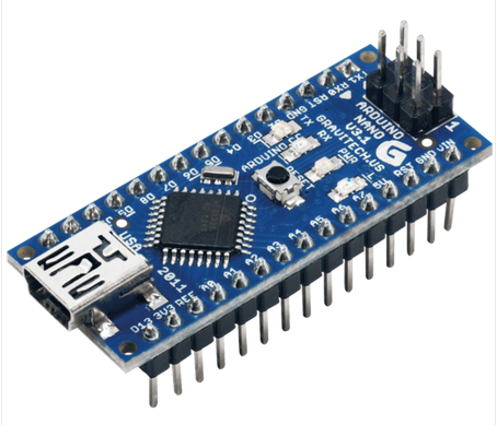
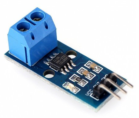
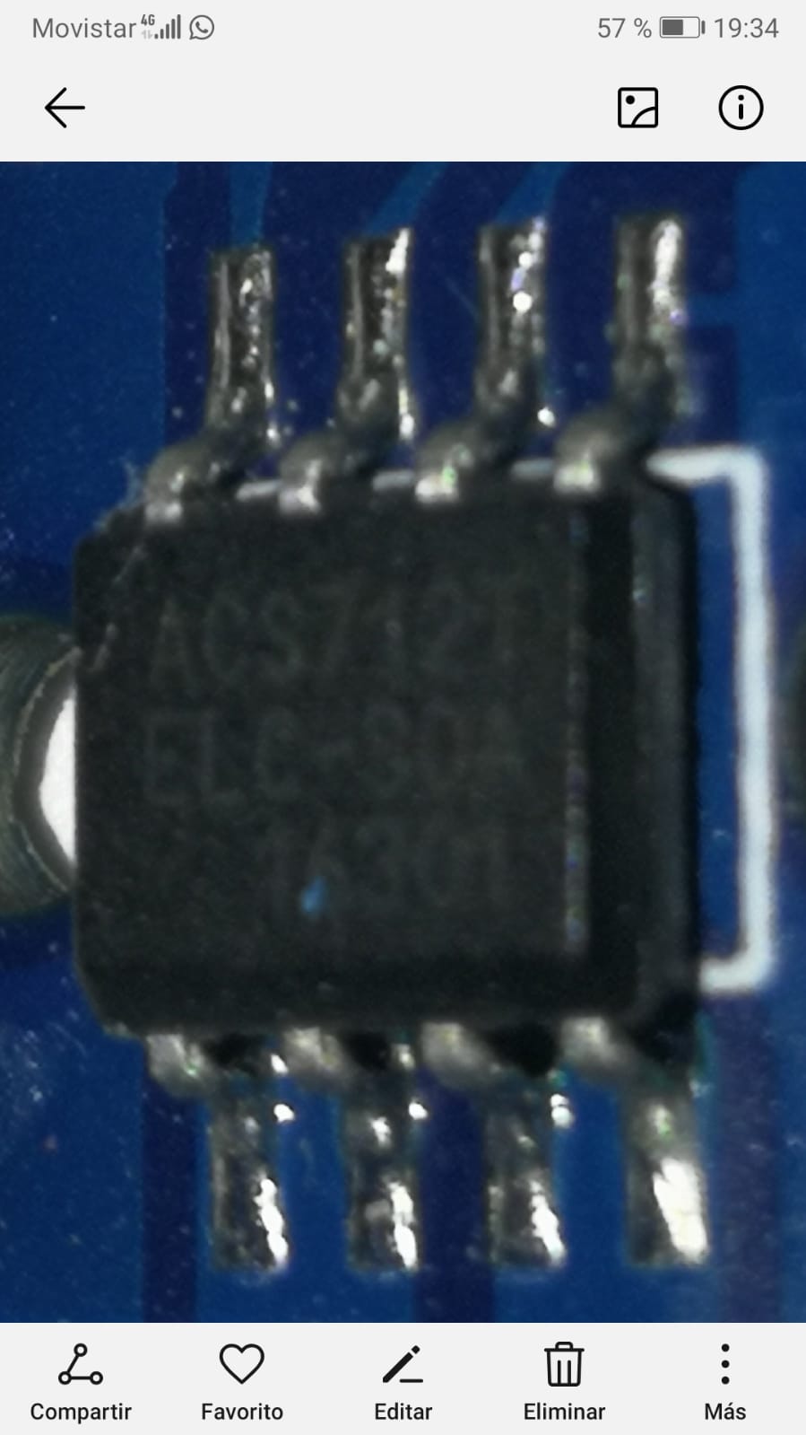
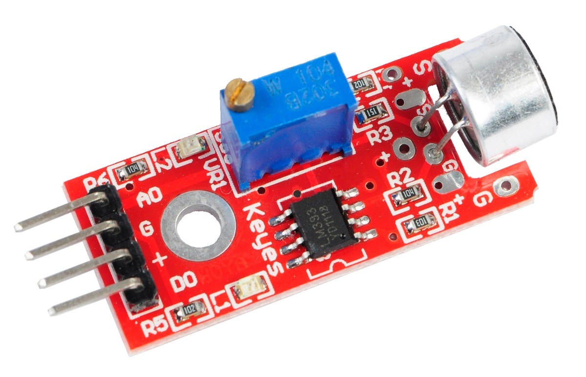
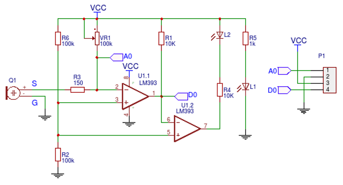
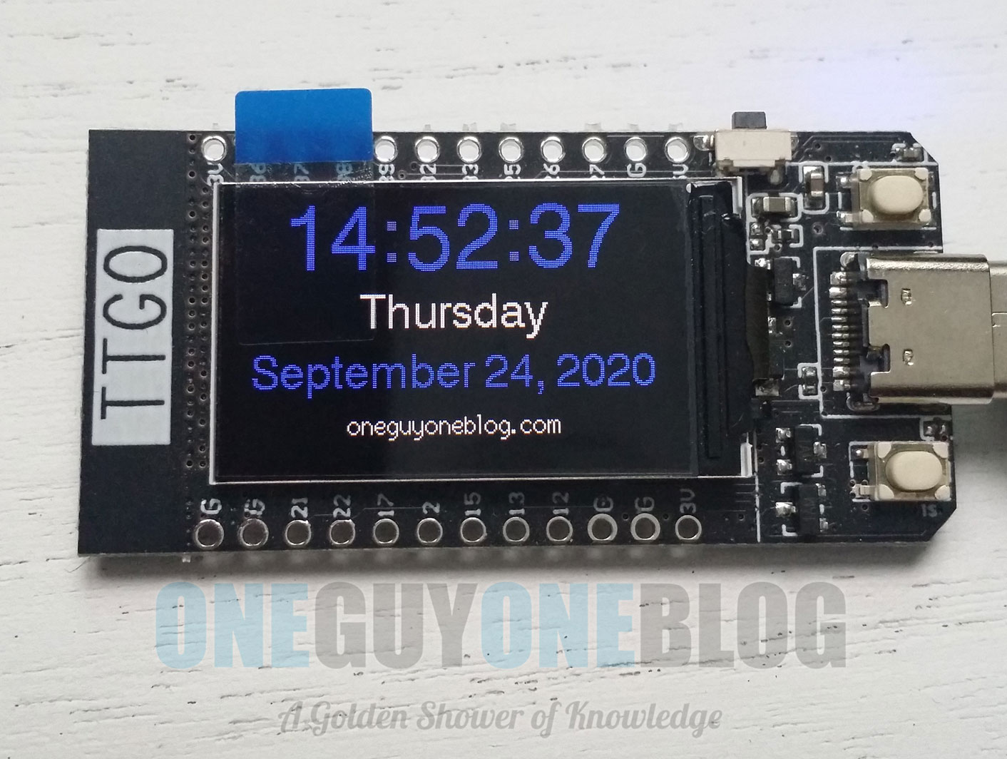
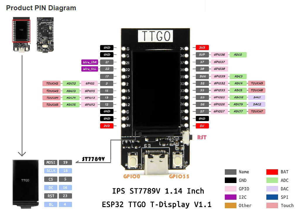
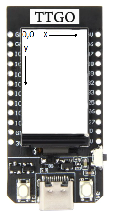
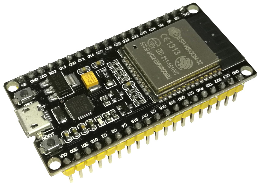


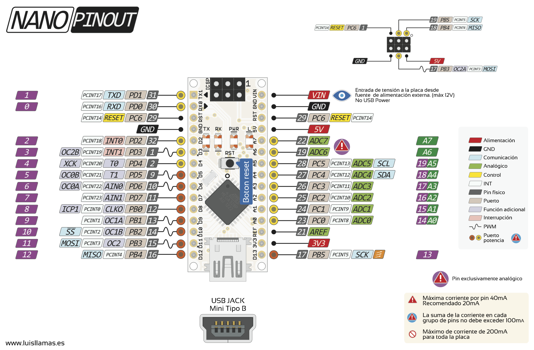