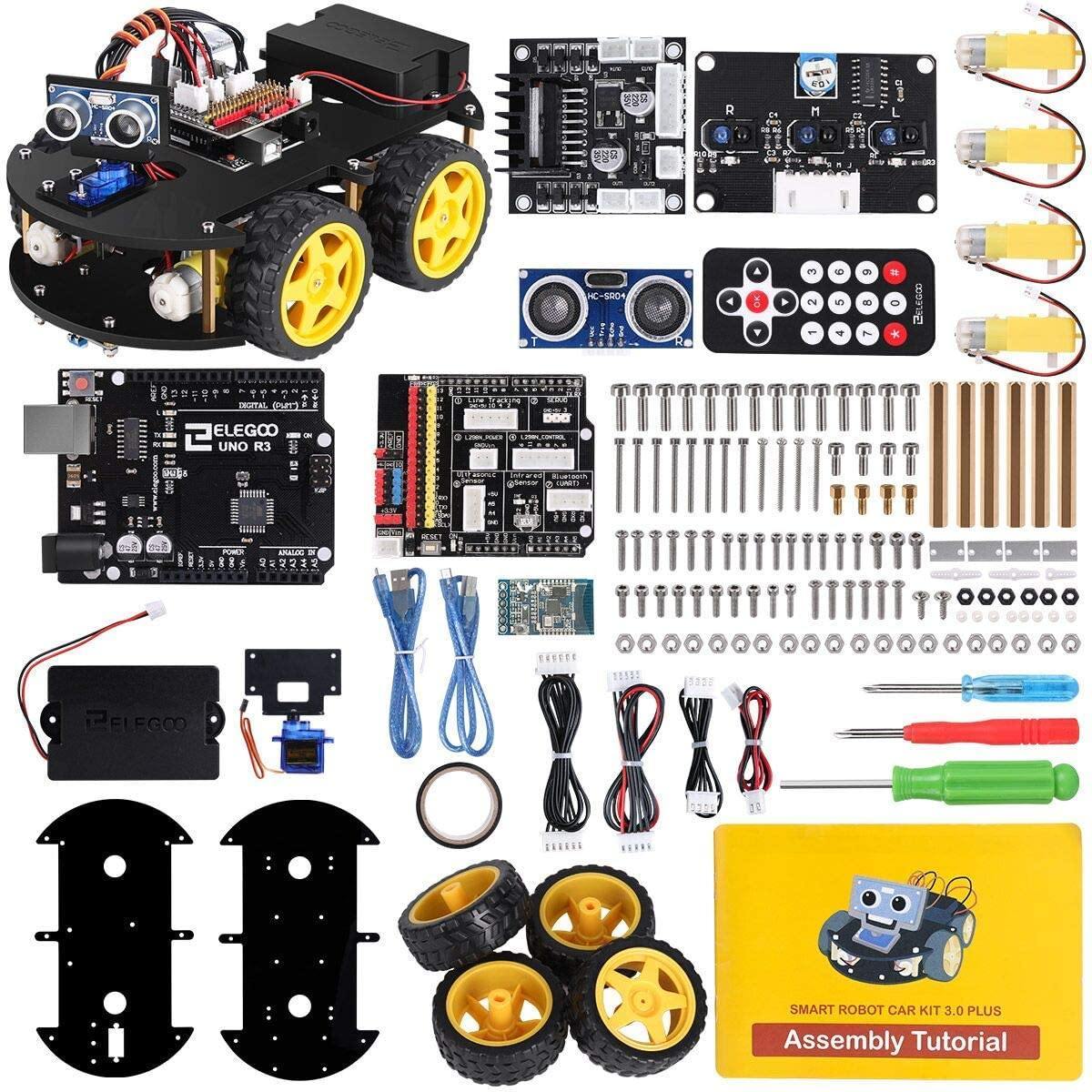
Elegoo Smart Robot Car 3.0 Plus
IAV, 20210106 - Elegoo Smart Robot Car 3.0 plus (with an Arduino "Uno") + 2x NRF24L01 modules + 2x YL-105
Homepage
Some URLs, manuals, tutorials :
contingut
- tires - 4 pcs
- DC motor - 4 pcs
- remote control - 1 pc
- USB cable type B - 1 pc
- USB cable type micro - 1 pc
- cell box - 1 pc {only used by servos}
- dead plate - 1 pc
- cable pack - 1 pc
- servo fasten plate (not for assembly) - 1 pc
- screw pack - 6 pcs
- screwdriver - 3 pcs
- insulation tape - 1 pc
- ultrasonic sensor module holder and SG90 micro servo - 1 pc
- Arduino UNO - 1 pc
- L298N dual H-bridge - 1 pc
- DX-BT16 bluetooth module - 1 pc
- IO expansion board / car shield - 1 pc
- line tracking module - 1 pc
- HC-SR04 ultrasonic sensor module - 1 pc
The expansion board uses XH2.54 interfaces
The USB-micro port is used to charge the battery
Battery status indicator : lights up in green during charging,
will turn off once the battery is fully charged.
The USB-B type port is used for uploading programs from PC
bluetooth module and uploading of programs from PC
When uploading a program frpm PC to Arduino, unplug ther bluetooth module first, as DX-BT16 communicates with UNO through the RX/TX pin on the shield.
If bluetooth is connected, the "upload" operation at Arduino IDE v2 produces :
avrdude: stk500_recv(): programmer is not responding
avrdude: stk500_getsync() attempt 1 of 10: not in sync: resp=0x00
avrdude: stk500_recv(): programmer is not responding
avrdude: stk500_getsync() attempt 2 of 10: not in sync: resp=0x00
avrdude: stk500_recv(): programmer is not responding
avrdude: stk500_getsync() attempt 3 of 10: not in sync: resp=0x00
User abort
description of parts
- L298N - dual H-bridge motor driver -
L298N
- HC-SR04 - ultrasonic sensor module - description
- SG90 - micro servo
- DX-BT16 bluetooth UART module
cor del sistema : Arduino UNO R3 board
Em falten les especs del Arduino "Uno"
The Elegoo Uno is a microcontroller board based on the ATmega328.
It has 14 digital input/output pins (of which 6 can be used as PWM outputs), 6 analog inputs,
a 16 MHz crystal oscillator, a USB connection, a power jack, an ICSP header, and a reset button.
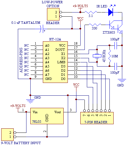
Robot Car IO pin connection table
Veure el detall de la placa I/O
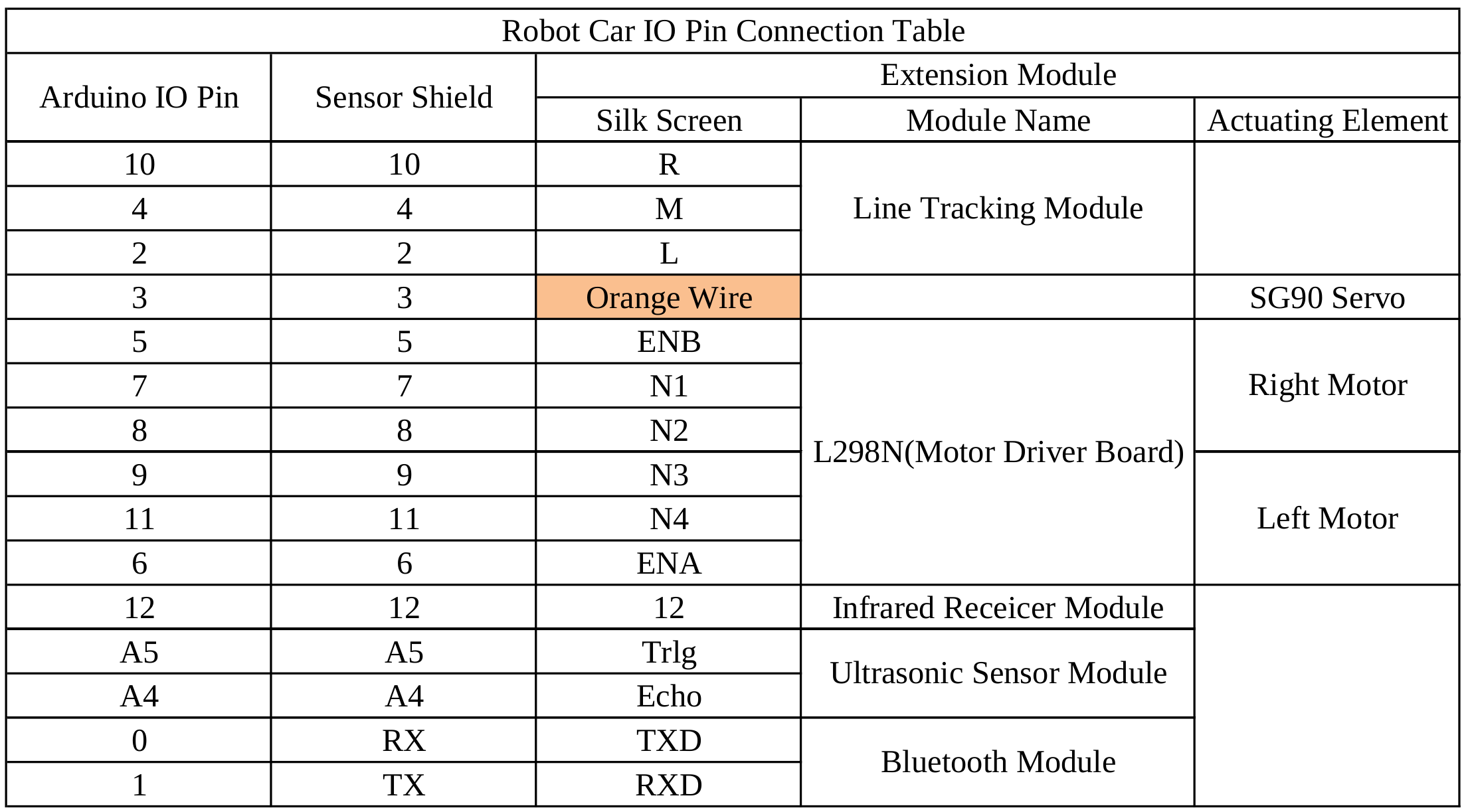
Valor comprovats en el meu :
#define LED_Pin 13 /* LED fixe */
#define RECV_PIN 12 /* Arduino pin connected to the IR Receiver */
#define IR_RECEIVE_PIN 12
#define ECHO_PIN A4 /* Arduino pins connected to the Ultrasonic sensor module */
#define TRIG_PIN A5
#define ENA 5 /* Arduino pins connected to the Motor drive module */
#define ENB 6 /* ENA = left motor, ENB = right motor */
/* error al esquema : hi posa ENA 6 ; ENB 5 */
#define IN1 7
#define IN2 8
#define IN3 9
#define IN4 11
#define LineTeacking_Pin_Right 10 /* Arduino pins connected to the IR line tracking module */
#define LineTeacking_Pin_Middle 4
#define LineTeacking_Pin_Left 2
#define PIN_Servo 3 /* SG90 servo */
sensor ultrasonic SR04
HC-SR04 provides 2 cm - 400 cm non-contact measurement with an accuracy of 3 mm. This module consists of an ultrasonic transmitter, a receiver, and the control circuit.
SR04.zip library
from
robotCar
Codi minim SR04 :
#include "SR04.h"
#define TRIG_PIN A5 // see
IO pin table
#define ECHO_PIN A4
SR04 sr04 = SR04(ECHO_PIN,TRIG_PIN);
long a;
void InitSerial(void)
{
Serial.begin(115200) ; // init serial
while (!Serial) ; // wait for Serial to become available
delay(4000) ; // to be able to connect Serial Monitor after reset or power up and before first print out
} // InitSerial()
void setup() {
InitSerial() ;
Serial.println( "*** SR04 setup ***" ) ;
}
void loop() {
a=sr04.Distance();
Serial.print(a);
Serial.println("cm");
delay(1000);
}
SR04.txt
from
robotCar
per moure el sistema ultrasonic : SG90 micro servo
servo.zip library
Les operacions habituals son :
myservo.attach( 3 ) ; // servo.attach(pin)
myservo.attach( 3, 700, 2500 ) ; // servo.attach(pin, min, max)
myservo.write( 90 ) ; // angle: the value to write to the servo, from 0 to 180 -
arduino.cc
servo.attach documentation
Per exemple, per esborrar el programa anterior i deixar el robot aturat, podem fer :
// 0_set_to_center_position
// posicio de "descans" del robot
// posem el servo mirant endevant
// despres de posar-lo a l'esquerra, per a que hi hagi un moviment minim
// despres, el mourem a la dreta i de volta per cada caracter que envii el Serial Monitor
#include <Servo.h>
Servo myServo ;
int iRC = 0 ;
int myFlop(int x, int y) {
int flopRC = 0 ;
myServo.write(x); // 0 = move servos to the right
delay(1000);
myServo.write(y); // 90 = move servos to center position -> 90°
return flopRC;
}
void setup(){
Serial.begin(115200);
while (!Serial) ; // wait for Serial to become available.
delay(4000); // to be able to connect Serial Monitor after reset or power up and before first print out.
Serial.println("*** servo center IR v 1.b setup.");
myServo.attach(3);
iRC = myFlop( 180, 90 ) ;
}
void loop(){
Serial.println("*** servo center IR v 1.b loop ***");
if ( Serial.available() > 0 ) {
char c = Serial.read() ;
Serial.print("+++ got ");
Serial.println(c);
iRC = myFlop( 0, 90 ) ;
}
delay(1000);
}
Codi minim SG90, servo q mou el sistema de ultrasons :
#include <Servo.h>
Servo myservo; // create servo object to control a servo ; 12 servo objects can be created on most boards
int pos = 0; // variable to store the servo position
void setup() {
myservo.attach(3); // attach the servo on pin 3 to the servo object
}
void loop() {
for (pos = 0; pos <= 180; pos += 1) { // goes from 0 degrees to 180 degrees (in steps of 1 degree)
myservo.write(pos); // tell servo to go to position in variable 'pos'
delay(15); // wait 15 ms for the servo to reach the position
}
for (pos = 180; pos >= 0; pos -= 1) { // goes from 180 degrees to 0 degrees
myservo.write(pos); // tell servo to go to position in variable 'pos'
delay(15); // wait 15 ms for the servo to reach the position
}
}
servo.txt
from
robotCar
L298 per moure les rodes
The robot consists of 4 DC motors driven by a H-bridge with dual output, connecting the two left wheels and the two right ones to its outputs.
The robot car kit uses L298 Dual H-Bridge Motor Driver module
(datasheet) to control the DC motors on the car.
Les dues rodes de cada cantó van sempre juntes ...
Taula per determinar la direcció i els girs :
car left wheels right wheels IN1 IN2 IN3 IN4
F F F 1 0 0 1
B B B 0 1 1 0
right F B 1 0 1 0
left B F 0 1 0 1
stop stop stop 0 0 0 0
1 1 1 1
Codi minim L298, H-bridge per moure les rodes :
#define ENA=6;
#define ENB=5;
#define N1=7;
#define N2=8;
#define N3=9;
#define N4=11;
#define carSpeed 200 //
void forward(){
digitalWrite(IN1, HIGH);
digitalWrite(IN2, LOW);
digitalWrite(IN3, LOW);
digitalWrite(IN4, HIGH);
Serial.println("Forward ");
}
void setup(){
pinMode(ENA,OUTPUT);
pinMode(ENB,OUTPUT);
pinMode(N1,OUTPUT);
pinMode(N2,OUTPUT);
pinMode(N3,OUTPUT);
pinMode(N4,OUTPUT);
analogWrite(ENA, carSpeed) ; // the PWM value is 0~255, 0 means always OFF, 255 means always ON.
analogWrite(ENB, carSpeed) ;
digitalWrite(ENA,HIGH); // enable left motor
digitalWrite(ENB,HIGH); // enable right motor
}
void loop(){
digitalWrite(N1,HIGH); // forward
digitalWrite(N2,LOW);
digitalWrite(N3,LOW);
digitalWrite(N4,HIGH);
}
dcMotor_1.txt
from
robotCar
assembly sequence
- line tracking module - 4 screws at front
- L298N dual H-bridge motor driver - heat sink in opposite direction of front
- 4 motors
- UNO R3 board
- I/O expansion board
- bluetooth module
- cell box or lithium battery
- HC-SR04 ultrasonic sensor module and SG90 micro servo - 2 "eyes" on front and servo that moves it
startup problems
Solved by euservice@elegoo.com
car goes backward when pushing "forward" button
Problem is caused by the L298N module, mounted reversed
car does not move when starting "obstacle avoidance" mode, key "2"
I think it’s the problem of the main code. Please download the tutorial following these steps :
- access support files
- on the left you select "Robot Kits"
- select "ELEGOO Smart Robot Car Kit V3.0 Plus
- unzip "ELEGOO Smart Robot Car Kit V3.0 Plus2020.12.31.zip" file
Please refer to lesson 0 to install Arduino IDE on your computer. It will teach you how to upload code to the robot car.
Please refer to lesson 3 to add the IRremote library into Arduino IDE {***}.
Then upload the SmartCar_Core_20201211.ino code file in lesson 6 to the robot car.
The latest code would help you solve the problem.
built-in provided programs
We have already uploaded programs into the smart robot : see SmartCar_Core_20201211.ino under folder "Lesson 6 SmartCar Multi function"
If you want to modify the code and upload to the car again, please refer to the tutorial from
http://www.elegoo.com/download 
When uploading codes (from PC),
please remove the bluetooth module from the expansion board,
because the serial port for uploading codes and bluetooth communication
use the same RX/TX pin and there will be conflicts.
You can mount the bluetooth module again after the upload.
Functions
There are 4 modes of Elegoo Smart Robot Car, which are :
- bluetooth mode
- IR - remote control mode
- line tracking mode - key #1
- obstacle avoidance mode - key #2
How do you select the Smart Robot Car mode ?
control the Smart Robot Car using the IR Remote
User manual, page 22 :
- upload into the car the file "Infrared_remote_control_car.ino"
located at "/home/sebas/dades/elegoo/ELEGOO Smart Robot Car Kit V3.0 Plus2020.12.31/English/Lesson 3 Infrared Remote Control Car/Infrared_remote_control_car"
if "compilation error : IRremote.h no such file", then
github
# IRremote Arduino Library
This library enables you to send and receive using infra-red signals on an Arduino.
## Version - 2.1.0
## Installation
1. Navigate to the [Releases] page :
https://github.com/z3t0/Arduino-IRremote/releases
2. Download the latest release.
3. Extract the zip file
4. Move the "IRremote" folder that has been extracted to your libraries directory.
5. Make sure to delete Arduino_Root/libraries/RobotIRremote.
"Arduino_Root" refers to the install directory of Arduino.
The library RobotIRremote has similar definitions to IRremote and causes errors.
Or better /home/sebas/dades/elegoo/ELEGOO Smart Robot Car Kit V3.0 Plus2020.12.31/English/Lesson 3 Infrared Remote Control Car/Lesson 3 Infrared remote control car.pdf -> IRremote.zip
- IDE -> Sketch -> Include Library -> Add .ZIP Library
- find IRremote.zip
- restart IDE
Missatge interessant :
990 -> IR blink v 1.a setup.
118 -> Thank you for using the IRremote library!
150 -> It seems, that you are using a old version 2.0 code / example.
215 -> This version is no longer supported!
246 -> Please use one of the new code examples from the library,
310 -> available at "File > Examples > Examples from Custom Libraries / IRremote",
406 -> Or downgrade your library to version 2.6.0.
438 -> Start with the SimpleReceiver or SimpleSender example.
503 -> The examples are documented here:
535 -> https://github.com/Arduino-IRremote/Arduino-IRremote#examples-for-this-library
631 -> A guide how to convert your 2.0 program is here:
695 -> https://github.com/Arduino-IRremote/Arduino-IRremote#converting-your-2x-program-to-the-4x-version
791 -> Thanks
M'agradaria saber de on surt ... on es el font del texte ...
Conversió de versió 2 a versió 4 :
- IRreceiver and IRsender object have been added and can be used without defining them, like the well known Arduino Serial object.
- Just remove the line IRrecv IrReceiver(IR_RECEIVE_PIN); and/or IRsend IrSender; in your program.
Replace all occurrences of IRrecv. or irrecv. with IrReceiver and replace all IRsend or irsend with IrSender.
- Since the decoded values are now in IrReceiver.decodedIRData and not in results any more, remove the line decode_results results or similar.
- Like for the Serial object,
call IrReceiver.begin(IR_RECEIVE_PIN, ENABLE_LED_FEEDBACK) or IrReceiver.begin(IR_RECEIVE_PIN, DISABLE_LED_FEEDBACK)
instead of the IrReceiver.enableIRIn() or irrecv.enableIRIn() in setup().
For sending, call IrSender.begin(); in setup().
If IR_SEND_PIN is not defined (before the line #include <IRremote.hpp>) you must use e.g. IrSender.begin(3, ENABLE_LED_FEEDBACK, USE_DEFAULT_FEEDBACK_LED_PIN);
- Old decode(decode_results *aResults) function is replaced by simple decode().
So if you have a statement if (irrecv.decode(&results)) replace it with if (IrReceiver.decode()).
- The decoded result is now in in IrReceiver.decodedIRData and not in results any more.
Therefore replace any occurrences of results.value and results.decode_type (and similar)
to IrReceiver.decodedIRData.decodedRawData and IrReceiver.decodedIRData.protocol.
Resum de canvis a fer :
remove IRrecv IrReceiver(IR_RECEIVE_PIN)
remove IRsend
remove IrSender
replace IRrecv. with IrReceiver.
replace irrecv. with IrReceiver. // irrecv.resume(); -> IrReceiver.resume(); // enable receiving next value
replace IRsend with IrSender
replace irsend with IrSender
remove decode_results results
replace in setup() IrReceiver.enableIRIn() with IrReceiver.begin(IR_RECEIVE_PIN, ENABLE_LED_FEEDBACK) or IrReceiver.begin(IR_RECEIVE_PIN, DISABLE_LED_FEEDBACK)
replace in setup() irrecv.enableIRIn() with IrReceiver.begin(IR_RECEIVE_PIN, ENABLE_LED_FEEDBACK) or IrReceiver.begin(IR_RECEIVE_PIN, DISABLE_LED_FEEDBACK)
insert in setup IrSender.begin()
replace if(irrecv.decode(&results)) with if(IrReceiver.decode())
replace results.value with IrReceiver.decodedIRData.decodedRawData
replace results.decode_type with IrReceiver.decodedIRData.protocol
Determina els codis de les tecles (using "Infrared_remote_control_car.ino") :
up 3108437760
left 3141861120
down 3927310080
right 3158572800
OK 3208707840
(*) 3175284480
(#) 3041591040
Codi minim IR :
#include <IRremote.hpp>
#define IR_RECEIVE_PIN 12 // Elegoo Smart Robot Car 3.0 Plus - see
IO pin table
// https://github.com/Arduino-IRremote/Arduino-IRremote#converting-your-2x-program-to-the-4x-version
void InitSerial(void)
{
Serial.begin(115200) ; // init serial
while (!Serial) ; // wait for Serial to become available
delay(4000) ; // to be able to connect Serial Monitor after reset or power up and before first print out
} // InitSerial()
void setup() {
InitSerial() ;
Serial.println("*** IR code v 1.a setup ***");
pinMode(IN1,OUTPUT);
pinMode(IN2,OUTPUT);
pinMode(IN3,OUTPUT);
pinMode(IN4,OUTPUT);
pinMode(ENA,OUTPUT);
pinMode(ENB,OUTPUT);
stop();
// Just to know which program is running on my Arduino
Serial.println( "START " __FILE__ " from " __DATE__ "\r\nUsing library version " VERSION_IRREMOTE );
// irrecv.enableIRIn(); // old code
IrReceiver.begin(IR_RECEIVE_PIN, ENABLE_LED_FEEDBACK); // start the receiver, new code
Serial.println("IR code v 1.a enabled");
Serial.print( "Ready to receive IR signals of protocols: " );
printActiveIRProtocols(&Serial);
delay(4000); // to display a clean list
}
void loop() {
Serial.println("*** IR code v 1.a loop.");
if (IrReceiver.decode()) {
Serial.println(IrReceiver.decodedIRData.decodedRawData, HEX); // Print "old" raw data
IrReceiver.printIRResultShort(&Serial); // Print complete received data in one line
IrReceiver.printIRSendUsage(&Serial); // Print the statement required to send this data
// ...
IrReceiver.resume(); // Enable receiving of the next value
}
delay(1000) ; // wait 1 sec
}
Provides a list of supported protocols :
NEC/MEC2/Onkyo/Apple, Panasonic/Kassikye, Denon/Sharp, Sony, RCS, ACB, LG, JVC, Samsung, FAST, Mhynter,
Lego Power Functions, Bosewave, RagiQuest, Universal Pulse Distance Width, Hash
Nice video : IR by Paul McWhorter -
uses IRremote v.2.2.3 de'n "shirriff"
Un altre : DroneBot
control the Smart Robot with the Bluetooth APP
Al robot s'hi ha de posar "SmartCar_Core_20210127.ino" !!!
Jo nomes tinc "SmartCar_Core_20201211.ino"
Get it here !!
Also, user manual, page 24
- download "Elegoo BLE Tool" APP from APP Store in Google Play -> now called "ElegooKit"
the BLE tool is procided in the (E-SRCK V3.0 Plus 2020.12.31) zip file, as "ElegooBleTool_32.apk"
- open "ElegooKit" APP
- click the top left corner icon (four squares) to enter the robots list
- scroll down and select "Smart Robot Car Kit v3.0 Plus" to enter the control page
- tap the "bluetooth" icon (first of two icons on top right corner) to enter the bluetooth searching interface
- put you phone close to the Smart Robot Car (within 10 cm) - the APP will connect automatically to the Smart Robot Car
- "Rocker Control panel" :
- a) rocker control - rodona a l'esquerra
- b) stand by mode - boto quadrat baix al mig
- c) obstacle-avoidance mode - barra inclinada, a l'esquerra
- d) line-trancking mode - barra inclinada, a la dreta
20241114 - wrong robot (V4 selected)
Unable to connect the device.
Plase make sure the phone is connected to the wifi provided by the device.
mono-io-layer-error(113)
tracking mode
Apply the black tape on a light-colored surface to make a runway,
press the "1" button on the remote control, and the car will enter the Line Tracking Mode
and will move along the runway.
Press "OK" button to stop the movement.
obstacle avoidance mode
Press "2" button, and the car will enter the obstacle avoidance mode and automatically move forward.
When there are obstacles within 25 cm ahead, the car will automatically turn and choose another way
coding
See Elegoo Smart Robot Car Kit V3.0 Plus2020.12.31.zip,
from download , then
Arduino related products (support files) + "Robot kits" -
url :
//mars/home/nicolau/sebas/elegoo/'ELEGOO Smart Robot Car Kit V3.0 Plus2020.12.31.zip'
They use "Arduino-1.8.12-linux.zip"
lets connect the car to the PC
- open Arduino IDE
- connect the Development board to PC with USB
- open the directory where the AUTO_GO sketch is located :
nicolau@mars:~/sebas/elegoo/Lesson 1 Make The Car Move/AUTO_GO$ ls -al
2259 Oct 27 10:51 AUTO_GO.ino
- select the Arduino Uno board : "Tools" + "Board" + "Arduino Uno" - on IDE we see (bottom right)
Arduino Uno on /dev/ttyUSB0
- compile AUTO_GO to verify libraries : "Sketch" + "Verify/Compile" - on IDE we see (bottom left)
Done compiling
- important parameter : IDE + "Tools" + "Port"
Must be "/dev/ttyUSB0" for Arduino "Nano" and "dev/ttyACM0" for Arduino "Uno" (the Elegoo robot)
*** El IDE del Arduino sota Ubuntu "Mars" no es conecta al Arduino Uno, pero si sota Windows o Linux Minie ***
El xip USB pel Uno del Elegoo és un "Holtek HT42B534-2" en lloc del habiutual "CH341" -
arduino uno at mars
com programar el Elegoo des Ubuntu
- conectem el Arduino "Nano" al USB 2.0
- amb el IDE, carreguem "File -> Examples -> 01.Basics -> Blink" al "Nano" i verifiquem que funciona
- desconectem el "Nano" i hi posem el "Uno", el robot
- comprovem que desapareix "/dev/ttyUSB0"
- al IDE, escollim el port "/dev/ttyACM0"
- carreguem el programa al Arduino des el IDE i comprovem que funciona
programs to test all robot parts
posicionar el servo el centre i res mes
Aquest es el codi que deixarem al Arduino quan no tingui "res" mes
No volem pas que es "desperti" i comenci a fer coses, oi ?
nicolau@mars:~$ cat /home/nicolau/Arduino/my_code/set_to_center_position/set_to_center_position.ino
sebas@minie:~$ cat /home/sebas/dades/elegoo/codi/0_set_to_enter_position/0_set_to_center_position.ino
// www.elegoo.com
// posicio de "descans" del robot
// posem el servo mirant endevant ...
// ... despres de posar-lo a la dreta, per a que hi hagi un moviment minim
#include <Servo.h>
Servo myservo;
void setup(){
myservo.attach(3);
myservo.write(0); // move servos to the right
delay(1000);
myservo.write(90); // move servos to center position -> 90°
}
void loop(){
}
posicionar el servo a 0-90-180 graus en bucle
nicolau@mars:~$ cat /home/nicolau/sebas/elegoo/codi/1_posiciona_servo_0_90_180/1_posiciona_servo_0_90_180.ino
sebas@minie:~$ cat /home/sebas/dades/elegoo/codi/1_posiciona_servo_0_90_180/1_posiciona_servo_0_90_180.ino
// https://dronebotworkshop.com/elegoo-robot-car-part-3/
#include <Servo.h>
Servo myservo;
void setup(){
myservo.attach(3);
}
void loop(){
myservo.write(90); // move servos to center position -> 90°
delay(1000);
myservo.write(180);
delay(1000);
myservo.write(90);
delay(1000);
myservo.write(0);
delay(1000);
}
posicionar el servo de 0 a 180 graus de un en un i en bucle
nicolau@mars:~$ cat /home/nicolau/sebas/elegoo/codi/2_gira_servo_180_graus_de_1_en_1/2_gira_servo_180_graus_de_1_en_1.ino
sebas@minie:~$ cat /home/sebas/dades/elegoo/codi/2_gira_servo_180_graus_de_1_en_1/2_gira_servo_180_graus_de_1_en_1.ino
// https://community.particle.io/t/servo-h-library-included-with-arduino-solved/1209/3
#include <Servo.h>
Servo myservo ; // create servo object to control a servo
// pins for the HC-SR04 ultrasonic sensor
int Echo = A4 ;
int Trig = A5 ;
// constants to control the L298N H-Bridge
#define ENA 5
#define ENB 6
#define IN1 7
#define IN2 8
#define IN3 9
#define IN4 11
// user vars :
int pos = 0 ; // store the servo position
int iDelay = 15 ; // set global delay
// ===
void InitSerial(void)
{
Serial.begin(115200) ; // init serial
while (!Serial) ; // wait for Serial to become available
delay(4000) ; // to be able to connect Serial Monitor after reset or power up and before first print out
} // InitSerial()
void setup()
{
InitSerial() ;
myservo.attach( 3 ) ; // attach the servo on pin 3 to the servo object
}
// ===
void loop()
{
for(pos = 0; pos < 180; pos += 1) // goes from 0 degrees to 180 degrees in steps of 1 degree
{
myservo.write(pos); // tell servo to go to position in variable 'pos'
Serial.println( pos ) ;
delay( iDelay ); // wait 15ms for the servo to reach the position
}
for(pos = 180; pos>=1; pos-=1) // goes from 180 degrees to 0 degrees in steps of 1 degree
{
myservo.write(pos); // tell servo to go to position in variable 'pos'
Serial.println( pos ) ;
delay( iDelay); // wait 15ms for the servo to reach the position
} ;
} ;
En el T440 es troba a "c:\sebas\arduino\2_gira_servo_180_graus_de_1_en_1\2_gira_servo_180_graus_de_1_en_1.ino"
turn car to left and then to right
nicolau@mars:~/sebas/elegoo/Lesson 1 Make The Car Move/AUTO_GO$ cat AUTO_GO.ino
sebs@minie:~$ cat /home/sebas/dades/elegoo/ELEGOO Smart Robot Car Kit V3.0 Plus2020.12.31/English/Lesson 1 Make The Car Move/AUTO_GO/AUTO_GO.ino
//www.elegoo.com
// The direction of the car's movement :
// ENA ENB IN1 IN2 IN3 IN4 Description in "serial monitor"
// HIGH HIGH HIGH LOW LOW HIGH car is runing forward
// HIGH HIGH LOW HIGH HIGH LOW car is runing back
// HIGH HIGH LOW HIGH LOW HIGH car is turning left
// HIGH HIGH HIGH LOW HIGH LOW car is turning right
// HIGH HIGH LOW LOW LOW LOW car is stoped
// HIGH HIGH HIGH HIGH HIGH HIGH car is stoped
// LOW LOW N/A N/A N/A N/A car is stoped
//define L298n module IO pin
#define ENA 5
#define ENB 6
#define IN1 7
#define IN2 8
#define IN3 9
#define IN4 11
void forward(){
digitalWrite(IN1,HIGH); // set IN1 high level
digitalWrite(IN2,LOW); // set IN2 low level
digitalWrite(IN3,LOW); // set IN3 low level
digitalWrite(IN4,HIGH); // set IN4 high level
Serial.println("Forward"); // send message to serial monitor
}
void back(){
digitalWrite(IN1,LOW);
digitalWrite(IN2,HIGH);
digitalWrite(IN3,HIGH);
digitalWrite(IN4,LOW);
Serial.println("Back");
}
void left(){
digitalWrite(IN1,LOW);
digitalWrite(IN2,HIGH);
digitalWrite(IN3,LOW);
digitalWrite(IN4,HIGH);
Serial.println("Left");
}
void right(){
digitalWrite(IN1,HIGH);
digitalWrite(IN2,LOW);
digitalWrite(IN3,HIGH);
digitalWrite(IN4,LOW);
Serial.println("Right");
}
void InitSerial(void)
{
Serial.begin(115200) ; // init serial
while (!Serial) ; // wait for Serial to become available
delay(4000) ; // to be able to connect Serial Monitor after reset or power up and before first print out
} // InitSerial()
void setup() {
InitSerial() ;
Serial.println( "*** AUTO_GO setup ***" ) ;
pinMode(ENA,OUTPUT);
pinMode(ENB,OUTPUT);
pinMode(IN1,OUTPUT); // before using io pin, pin mode must be set
pinMode(IN2,OUTPUT);
pinMode(IN3,OUTPUT);
pinMode(IN4,OUTPUT);
digitalWrite(ENA,HIGH); // enable L298n A channel
digitalWrite(ENB,HIGH); // enable L298n B channel
}
// repeat execution
void loop() {
forward(); // go forward
delay(1000);
back(); // go back
delay(1000);
left(); // turn left
delay(1000);
right(); // turn right
delay(1000);
}
change motor speed
nicolau@mars:~/sebas/elegoo/ELEGOO Smart Robot Car Kit V3.0 Plus2020.12.31/English/Lesson 1 Make The Car Move/speed_control$ cat speed_control.ino
sebas@minie:~$ cat /home/sebas/dades/elegoo/ELEGOO Smart Robot Car Kit V3.0 Plus2020.12.31/English/Lesson 1 Make The Car Move/speed_control/speed_control.ino
//www.elegoo.com
#define ENA 5
#define ENB 6
#define IN1 7
#define IN2 8
#define IN3 9
#define IN4 11
void setup() {
pinMode(IN1,OUTPUT);
pinMode(IN2,OUTPUT);
pinMode(IN3,OUTPUT);
pinMode(IN4,OUTPUT);
pinMode(ENA,OUTPUT);
pinMode(ENB,OUTPUT);
}
void loop() {
// go forward
digitalWrite(IN1,HIGH);
digitalWrite(IN2,LOW);
digitalWrite(IN3,LOW);
digitalWrite(IN4,HIGH);
// reduce speed
for(int i = 255; i >= 0; i--){
analogWrite(ENB,i);
analogWrite(ENA,i);
delay(20);
}
// stop
analogWrite(ENB,0); //speed = 0
analogWrite(ENA,0);
delay(1000);
// go back
digitalWrite(IN1,LOW);
digitalWrite(IN2,HIGH);
digitalWrite(IN3,HIGH);
digitalWrite(IN4,LOW);
// increase speed
for(int i = 0; i <= 255; i++){
analogWrite(ENB,i);
analogWrite(ENA,i);
delay(20);
}
// stop
digitalWrite(ENB,LOW); // motor is off
digitalWrite(ENA,LOW);
delay(2000);
}
Servo Test sketch
Here is the “Servo Debug” sketch that Elegoo has provided:
// www.elegoo.com
#include <Servo.h>
Servo myservo;
void setup(){
myservo.attach(3);
myservo.write(90); // move servos to center position -> 90°
}
void loop(){
}
drone bot workshop
Collision Avoidance sketch
Here is the collision avoidance sketch provided by Elegoo:
// www.elegoo.com
#include <Servo.h> // servo library
Servo myservo; // create servo object to control servo
int Echo = A4;
int Trig = A5;
#define ENA 5
#define ENB 6
#define IN1 7
#define IN2 8
#define IN3 9
#define IN4 11
#define carSpeed 150
int rightDistance = 0, leftDistance = 0, middleDistance = 0;
void forward(){
analogWrite(ENA, carSpeed);
analogWrite(ENB, carSpeed);
digitalWrite(IN1, HIGH);
digitalWrite(IN2, LOW);
digitalWrite(IN3, LOW);
digitalWrite(IN4, HIGH);
Serial.println("Forward");
}
void back() {
analogWrite(ENA, carSpeed);
analogWrite(ENB, carSpeed);
digitalWrite(IN1, LOW);
digitalWrite(IN2, HIGH);
digitalWrite(IN3, HIGH);
digitalWrite(IN4, LOW);
Serial.println("Back");
}
void left() {
analogWrite(ENA, carSpeed);
analogWrite(ENB, carSpeed);
digitalWrite(IN1, LOW);
digitalWrite(IN2, HIGH);
digitalWrite(IN3, LOW);
digitalWrite(IN4, HIGH);
Serial.println("Left");
}
void right() {
analogWrite(ENA, carSpeed);
analogWrite(ENB, carSpeed);
digitalWrite(IN1, HIGH);
digitalWrite(IN2, LOW);
digitalWrite(IN3, HIGH);
digitalWrite(IN4, LOW);
Serial.println("Right");
}
void stop() {
digitalWrite(ENA, LOW);
digitalWrite(ENB, LOW);
Serial.println("Stop!");
}
// Ultrasonic distance measurement function
//
// The Distance_test function is used to drive the HC-SR04 ultrasonic sensor and measure the distance.
// It works by producing a pulse that goes low for 2 microseconds and then high for 20 microseconds.
// This pulse is used to drive the trig (trigger) input on the HC-SR04.
// Then the Arduino pulseIn function is used to measure the received pulse from the echo pin on the ultrasonic sensor.
// The result is divided by 58 to get the distance in centimeters, this result is returned by the function as an integer.
int Distance_test() {
digitalWrite(Trig, LOW);
delayMicroseconds(2);
digitalWrite(Trig, HIGH);
delayMicroseconds(20);
digitalWrite(Trig, LOW);
float Fdistance = pulseIn(Echo, HIGH);
Fdistance = Fdistance / 58;
return (int)Fdistance;
}
void InitSerial(void)
{
Serial.begin(115200) ; // init serial
while (!Serial) ; // wait for Serial to become available
delay(4000) ; // to be able to connect Serial Monitor after reset or power up and before first print out
} // InitSerial()
void setup() {
myservo.attach(3); // attach servo on pin 3 to servo object
InitSerial() ;
Serial.println( "*** collision avoidance setup ***" ) ;
pinMode(Echo, INPUT);
pinMode(Trig, OUTPUT);
pinMode(IN1, OUTPUT);
pinMode(IN2, OUTPUT);
pinMode(IN3, OUTPUT);
pinMode(IN4, OUTPUT);
pinMode(ENA, OUTPUT);
pinMode(ENB, OUTPUT);
stop();
}
void loop() {
myservo.write(90); // set servo position according to scaled value
delay(500);
middleDistance = Distance_test();
if(middleDistance <= 20) {
stop();
delay(500);
myservo.write(10);
delay(1000);
rightDistance = Distance_test();
delay(500);
myservo.write(90);
delay(1000);
myservo.write(180);
delay(1000);
leftDistance = Distance_test();
delay(500);
myservo.write(90);
delay(1000);
if(rightDistance > leftDistance) {
right();
delay(360);
}
else if(rightDistance < leftDistance) {
left();
delay(360);
}
else if((rightDistance <= 20) || (leftDistance <= 20)) {
back();
delay(180);
}
else {
forward();
}
}
else {
forward();
}
}
drone bot workshop
Line Following sketch
Let’s take a look at the Line Tracking Car sketch provided by Elegoo.
// www.elegoo.com
// Line Tracking IO define
#define LT_R !digitalRead(10)
#define LT_M !digitalRead(4)
#define LT_L !digitalRead(2)
#define ENA 5
#define ENB 6
#define IN1 7
#define IN2 8
#define IN3 9
#define IN4 11
#define carSpeed 150
void forward(){
analogWrite(ENA, carSpeed);
analogWrite(ENB, carSpeed);
digitalWrite(IN1, HIGH);
digitalWrite(IN2, LOW);
digitalWrite(IN3, LOW);
digitalWrite(IN4, HIGH);
Serial.println("go forward!");
}
void back(){
analogWrite(ENA, carSpeed);
analogWrite(ENB, carSpeed);
digitalWrite(IN1, LOW);
digitalWrite(IN2, HIGH);
digitalWrite(IN3, HIGH);
digitalWrite(IN4, LOW);
Serial.println("go back!");
}
void left(){
analogWrite(ENA, carSpeed);
analogWrite(ENB, carSpeed);
digitalWrite(IN1, LOW);
digitalWrite(IN2, HIGH);
digitalWrite(IN3, LOW);
digitalWrite(IN4, HIGH);
Serial.println("go left!");
}
void right(){
analogWrite(ENA, carSpeed);
analogWrite(ENB, carSpeed);
digitalWrite(IN1, HIGH);
digitalWrite(IN2, LOW);
digitalWrite(IN3, HIGH);
digitalWrite(IN4, LOW);
Serial.println("go right!");
}
void stop(){
digitalWrite(ENA, LOW);
digitalWrite(ENB, LOW);
Serial.println("Stop!");
}
void InitSerial(void)
{
Serial.begin(115200) ; // init serial
while (!Serial) ; // wait for Serial to become available
delay(4000) ; // to be able to connect Serial Monitor after reset or power up and before first print out
} // InitSerial()
void setup(){
InitSerial() ;
Serial.println( "*** line follower v 1.0 setup ***" ) ;
pinMode(LT_R,INPUT);
pinMode(LT_M,INPUT);
pinMode(LT_L,INPUT);
}
void loop() {
if(LT_M){
forward();
}
else if(LT_R) {
right();
while(LT_R);
}
else if(LT_L) {
left();
while(LT_L);
}
}
drone bot workshop
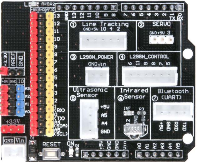
conexió amb l'exterior - I/O expansion card pinout
Mirem el esquema del pinout de la "expansion card" :
// Line Track LEDs
#define LT_LEFT 2
#define LT_MIDDLE 4
#define LT_RIGHT 10
// SG90 servo (moves the HC-SR04)
#define SERVO_SG90 3
// HC-SR04 ultrasonic sensor
int Echo = A4 ;
int Trig = A5 ;
// L298N H-Bridge
#define ENA 5
#define ENB 6
#define IN1 7
#define IN2 8
#define IN3 9
#define IN4 11
Queda molt clar el significat dels simbols vistos a la placa
Una pregunta : per que "ENA" és "define" mentre "Echo" és "int" ?
avrdude
avrdude: Version 6.3-20190619
Copyright (c) 2000-2005 Brian Dean,
http://www.bdmicro.com/
Copyright (c) 2007-2014 Joerg Wunsch
System wide configuration file is "/home/sebas/.arduino15/packages/arduino/tools/avrdude/6.3.0-arduino17/etc/avrdude.conf"
User configuration file is "/home/sebas/.avrduderc"
dubtes elegoo
- que es avrdude ?
github - tool for downloading and uploading the on-chip memories of Microchip’s AVR microcontrollers
- de vegades no puc pujar el codi al robot.
at IDE "Output" from Upload :
avrdude: stk500_recv(): programmer is not responding
avrdude: stk500_getsync() attempt 1 of 10: not in sync: resp=0x00
sebas@minie:~$ dmesg
cdc_acm 1-2:1.0: ttyACM0: USB ACM device
[ 1772.487052] usbhid 1-2:1.2: couldn't find an input interrupt endpoint
System log :
Nov 25 21:18:59 minie kernel: [ 2749.422840] cdc_acm 1-2:1.0: ttyACM0: USB ACM device
Nov 25 21:18:59 minie kernel: [ 2749.422961] usbhid 1-2:1.2: couldn't find an input interrupt endpoint
Nov 25 21:18:59 minie mtp-probe: checking bus 1, device 7: "/sys/devices/pci0000:00/0000:00:08.1/0000:05:00.3/usb1/1-2"
Nov 25 21:18:59 minie mtp-probe: bus: 1, device: 7 was not an MTP device
Nov 25 21:18:59 minie mtp-probe: checking bus 1, device 7: "/sys/devices/pci0000:00/0000:00:08.1/0000:05:00.3/usb1/1-2"
Nov 25 21:18:59 minie mtp-probe: bus: 1, device: 7 was not an MTP device
Nov 25 21:19:02 minie ModemManager[900]: <info> [base-manager] couldn't check support for device '/sys/devices/pci0000:00/0000:00:08.1/0000:05:00.3/usb1/1-2': not supported by any plugin
comunicació Raspberry - Raspberry per antena + conexió Rasberry a antena
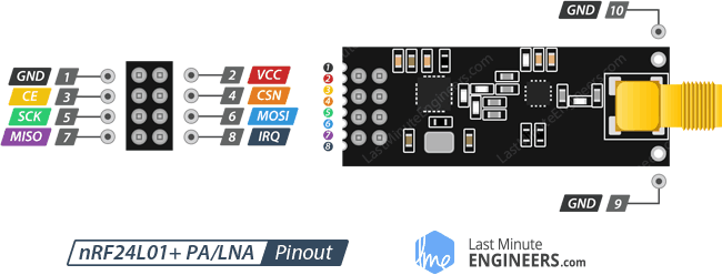
Tinc dues antenes NRF24L01 (amb antena externa) per conectar el Raspberry (o PC) al robot (Arduino)
antena specs PDFs : nRF24L01 ,
nRF24L01+
PA = Power Amplifier
LNA = Low-Noise Amplifier
CE = chip enable
CSN = chip select not
Em cal :
- esquema de conexionat del Raspberry a la antena
- software al Raspberry per "enviar"
- software al Raspberry per "rebre"
conexió Rasberry a antena
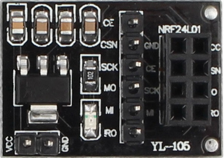
We use YL-105 card to provide 3,3 volts from Raspberry's 5 volts :
NRF24L01 Raspberry
CE [.] CE -> (15) GPIO22 Chip Enable
CSN [.] GND . . VCC CSN -> (24) GPIO08 + CE0_N Chip Select Not
SCK [.] CE . . CSN SCK -> (23) GPIO11 + SCLK Serial ClocK
MO [.] SCK . . MO MO -> (19) GPIO10 + MOSI Master Out (Slave In)
MI [.] MI . . IRQ MI -> (21) GPIO09 + MISO Master In (Slave Out)
IRQ [.] VCC -> (2) + 5 v
YL-105 GND -> (6) GND
VCC (5 volts) [.] [.] GND
Faig servir la conexio que ell recomana :
how to connect the the pins of the NRF24L01
Aixi, codificarem : ( detalls RF24 radio )
RF24 radio( <ce_pin>, <a>*10+<b> ) ; # for proper constructor to address correct spi device at /dev/spidev<a>.<b>
RF24 radio( 22, 0 ) ;
Detalls dels pins :
- CE (Chip Enable) is an active-HIGH pin.
When selected the nRF24L01 will either transmit or receive, depending upon which mode it is currently in.
- CSN (Chip Select Not) is an active-LOW pin and is normally kept HIGH.
When this pin goes low, the nRF24L01 begins listening on its SPI port (Serial Peripheral Interface) for data and processes it accordingly.
wifi communication + Arduino connection
cablejat antena - raspberry
Comencem aixi (radio/yl-105 -> RPi) :
- "GND" to GND, pin 39 (gray)
- "CE" to RPi GPIO#22, pin 15 (orange)
- "CSN" to RPi GPIO#08 "CE0", pin 24 (yellow)
- "SCK" to SCLK, GPIO#11, pin 23 (green)
- "MOSI" to Mosi, GPIO#10, pin 19 (blue)
- "MISO" to Miso, GPIO#09, pin 21 (purple)
- IRQ - not used, not connected
- "VCC" to +5, pin 4 (white)
wifi communication : get
lib_nfr24.py + example-nrf24-send-rpi.py + example-nrf24-recv-rpi.py from url
raspberry a raspberry - codi python
"PiZero" is running "sudo python example.nrf24-send-rpi.py"
"Odin" is running "sudo python example.nrf24-recv-rpi.py"
raspberry a raspberry - ODIN (receiver)
We run "[sag] $ sudo /home/sag/nrf24l01/example-nrf24-recv-rpi.py", from a direct "TV"
raspberry a raspberry - Pi0 (sender)
sebas@pi0alby:~/nrf24l01 $ sudo ./example-nrf24-send-rpi.py
Traceback (most recent call last):
File "./example-nrf24-send-rpi.py", line 16, in <module>
radio.begin(0, 17)
File "/home/sebas/nrf24l01/lib_nrf24.py", line 373, in begin
self.spidev.open(0, csn_pin)
IOError: [Errno 2] No such file or directory
sebas@pi0alby:~/nrf24l01 $ ls /dev/spi*
ls: cannot access '/dev/spi*': No such file or directory
SPI is not enabled
sebas@pi0alby:~/nrf24l01 $ cat /boot/config.txt | grep spi
#dtparam=spi=on
Lets go
$ sudo raspi-config
1 System Options
P4 SPI Enable/disable automatic loading of SPI kernel module
After a reboot, we have
sebas@pi0alby:~ $ ls /dev/spi*
0 crw-rw---- 1 root spi 153, 0 Jan 16 19:50 /dev/spidev0.0
0 crw-rw---- 1 root spi 153, 1 Jan 16 19:50 /dev/spidev0.1
Ara tenim
sebas@pi0alby:~/nrf24l01 $ sudo ./example-nrf24-send-rpi.py
[sudo] password for sebas:
STATUS = 0x03 RX_DR=0 TX_DS=0 MAX_RT=0 RX_P_NO=1 TX_FULL=1
RX_ADDR_P0-1 = 0x70707070f0 0xf9f9f9f9f9
RX_ADDR_P2-5 = 0xf0 0xf1 0xf1 0xf1
TX_ADDR = 0x70707070f0
RX_PW_P0-6 = 0x08 0x08 0x00 0x00 0x00 0x00
EN_AA = 0x0f
EN_RXADDR = 0x00
RF_CH = 0x18
RF_SETUP = 0xfe
CONFIG = 0x1f
DYNPD/FEATURE = 0x03 0x01
Data Rate = 1MBPS
Model = nRF24L01
CRC Length = 16 bits
PA Power = PA_HIGH
Sent: ['H', 'E', 'L', 'O', 1]
Received: Ack only, no payload
Sent: ['H', 'E', 'L', 'O', 2]
Received: Ack only, no payload
Sent: ['H', 'E', 'L', 'O', 3]
Received: Ack only, no payload
Aquest codi no em deix escollir el canal !
antena a antena - receiver code
A veure aquestos :
url
o millor
getting_started (both roles)
sag@r3:~/nrf24l01 $ cat 1_sag_rebre.py
#!/usr/bin/python3
# program to receive data using a NRF24 antenna
# https://nrf24.github.io/RF24/index.html
# https://github.com/jpbarraca/pynrf24/blob/master/examples/recv.py
import nrf24
radio = RF24(22, 0)
if not radio.begin():
raise RuntimeError("--- radio hardware is not responding")
adressa = [b"1Node", b"2Node"]
radio_number = 0 # receive
radio.setRetries( 15, 15 ) ;
radio.setPayloadSize( 16 ) ;
radio.setChannel( 3 ) ;
radio.setDataRate( NRF24.BR_250KBPS )
radio.setPALevel( RF24_PA_LOW ) # RF24_PA_MAX is default
radio.disableAckPayload()
radio.openWritingPipe( adressa[radio_number] ) # always uses pipe 0
radio.openReadingPipe( 1, adressa[not radio_number] ) # using pipe 1
radio.startListening() ;
radio.stopListening() ;
radio.printDetails() ; # see channel number
radio.startListening() ;
while True:
while not radio.available( ):
time.sleep(1000/1000000.0)
length = radio.getPayloadSize() # for static payload sizes
received_payload = radio.read(length)
print( received_payload )
chn = radio.channel
dades_hex = ':'.join(f'{i:02x}' for i in received_payload ) # convert data to hex
print(f'>>> dades rebudes canal {chn}: {dades_hex}.')
antena a antena - sender code
sebas@r0:~/python/nrf24 $ cat 1_send.py
antena a antena - URLs codi python
Exemples :
comunicació Raspberry - Arduino per antena
Em cal :
- esquema de conexionat del Raspberry a la antena - url
- software al Raspberry per "enviar" / "rebre"
- esquema de conexionat del Arduino a la antena
- software al Arduino per "rebre" / "enviar"
how to map the pipes format from Arduino to Raspberry
Raspberry :
address = [b"1Node", b"2Node"] # an address need to be a buffer protocol object (bytearray)
# sender receiver address
radio.openWritingPipe( address[radio_number] ) # always uses pipe 0 ; radio_number ( 0 = receiver, 1 = transmitter )
addresses = [[0xE0, 0xE0, 0xF1, 0xF1, 0xE0], [0xF1, 0xF1, 0xF0, 0xF0, 0xE0]]
radio.openWritingPipe(addresses[0]) # open the defined pipe for writing
TypeError: buf parameter must be bytes or bytearray
radio.printDetails() # print basic detals of radio
Arduino :
const uint64_t pipe = 0xE0E0F1F1E0LL ; // pipe address same as sender i.e. raspberry pi
radio.openReadingPipe(1, pipe) ; // start reading pipe
circuitdigest
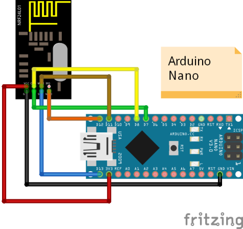
conexió Arduino 1na
NRF24L01 Arduino --------.
CE [.] CE -> (-) D9 Chip Enable Vin |
CSN [.] GND . . VCC CSN -> (-) D8 Chip Select Not GND |
SCK [.] CE . . CSN SCK -> (-) D13 Serial ClocK |
MO [.] SCK . . MO MO -> (-) D11 Master Out (Slave In) | Nano |
MI [.] MI . . IRQ MI -> (-) D12 Master In (Slave Out) | |
IRQ [.] VCC -> (-) Vin | D11 D14 |
YL-105 GND -> (-) GND | D12 D13 |
.--------------.
VCC (5 volts) [.] [.] GND
Aqui pots veure el pinout del Nano
conexió Arduino Uno (robot) a antena
. . .
comunicació Arduino - Raspberry per antena : codi Arduino "receiver"
Posem al IDE :
nicolau@mars:~/sebas/python/nrf24/arduino/rcv_sag$ cat rcv_sag.ino
// /home/nicolau/sebas/python/nrf24/arduino/docu/RF24-1.3.10/examples/GettingStarted/GettingStarted.ino
// https://forum.arduino.cc/index.php?topic=685951.0
// open "Tools" + "Serial Monitor" (CTRL + SHIFT + "M") and select 9600 baud
#include <SPI.h>
#include <RF24.h> //
RF24
// CE Pin uses GPIO number with BCM and SPIDEV drivers
// CS Pin addresses the SPI bus number at /dev/spidev<a>.<b>
RF24 radio( 9, 8 ) ; // CE, CSN
const byte oldaddress[6] = "00001";
// const byte address[5] = { 'R', 'x', 'A', 'A', 'A' } ;
const uint64_t adressa_pipe = 0xE0E0F1F1E0LL ; // pipe address same as sender i.e. raspberry pi
String szVersio = "v 1.2.a - nice loop" ;
String szIN = " " ; // data we receive
int iCnt = 0 ;
char text[32] = "" ;
void InitSerial(void)
{
Serial.begin(115200) ; // init serial
while (!Serial) ; // wait for Serial to become available
delay(4000) ; // to be able to connect Serial Monitor after reset or power up and before first print out
} // InitSerial()
void setup() {
InitSerial() ;
Serial.println( "*** RF24 receiver started ***" ) ;
Serial.println( szVersio ) ;
radio.begin();
radio.openReadingPipe( 1, address ) ;
radio.setPALevel( RF24_PA_MIN ) ;
radio.startListening();
}
void loop() {
if ( radio.available() ) {
szIN = " " ;
while (radio.available()) {
radio.read( &szIN, sizeof( szIN ) ) ;
} ;
radio.stopListening();
Serial.print( "+++ rcvd, lng(" ) ;
Serial.print( szIN.length() ) ;
Serial.print( "). " ) ;
Serial.println( szIN ) ;
radio.startListening() ;
}
Serial.print( ">>> bucle " ) ;
iCnt = iCnt + 1 ;
Serial.println( iCnt ) ;
}
I obtenim :
nRF24L01.h: No such file or directory
Read how to install Arduino libraries and install :
- get master.zip and rename ir "rf24.zip"
- open Arduino IDE and go to "Sketch", "Include Library", "add .zip library" and open the .zip file that you have just downloaded
- now the NRF24 library should be installed
- check "Sketch" + Include Library"
Ara ja podem compilar. Per pujar el codi al Nano cal anar a "Tools" + "Port" i escollir "/dev/ttyUSB0"
comunicació Arduino - Raspberry per antena : proves rspi send, arduino recv
- arduino : rcv_sag.ini + serial monitor
- pi0 : sebas@pi0alby:~/python/nrf24 $ ./1_send.py
comunicació Arduino - Raspberry per antena : codi Arduino "sender"
URLs Raspberry - antenes - Arduino
Elegoo help, links, etc
NRF24L01
The nRF24L01+ transceiver module is designed to operate in 2.4 GHz worldwide
ISM (Industrial, Scientific, and Medical) frequency band
and uses GFSK modulation for data transmission.
The data transfer rate can be one of 250kbps, 1Mbps and 2Mbps.
(url)
The nRF24L01+ transceiver module communicates over a 4-pin Serial Peripheral Interface (SPI) with a maximum data rate of 10Mbps.
All the parameters such as frequency channel (125 selectable channels),
output power (0 dBm, -6 dBm, -12 dBm or -18 dBm),
and data rate (250kbps, 1Mbps, or 2Mbps) can be configured through SPI interface.
Lower Data Rate - url
The nRF24L01+ offers highest receiver sensitivity at 250Kbps speed which is -94dBm.
However at 2MBps data rate, the receiver sensitivity drops to -82dBm.
If you speak this language, you know that the receiver at 250Kbps is nearly 10 times more sensitive than at 2Mbps.
That means the receiver can decode a signal that is 10 times weak.
The nRF24L01+ transceiver module uses a packet structure known as Enhanced ShockBurst :
- preamble, 0x55 or 0xAA
- address [3, 5] bytes
- PCF, 9 bits : payload length, 6bits ; PID, 2 bits ; NO_ACK, 1 bit
- payload [0, 32] bytes
- CRC [1, 2] bytes
Specs :
- rango: línea de visión de más de 800 metros (dejémoslo en 100)
- auto-reconocimiento y habilidades de retransmisión automática
- admite hasta seis canales de recepción de datos
- the NRF24L01 module works with the help of SPI communications
- worldwide 2.4GHz ISM band operation
- (nRF24L01+) 250kbps, 1Mbps and 2Mbps on air data rates - (nRF24L01) on the air data rate 1 or 2Mbps
- 11.3mA TX at 0dBm output power
En comprem un parell a
Amazon , junt amb una parella de YL-105, per 13 € tot !
NRF24L01 version
There are differences between nRF24L01 and nRF24L01+
- ACK_PAYLOAD - nRF24L01+ only, does not exist on nRF24L01
- speed - BR_250KBPS only accepted by nRF24L01+
How to check my radio version ?
NRF24L01 concepts
pipes :
pipes are called "logical channels" in the data sheet.
They constitute the (software) conduit/path through which data is sent from one nRF24 module to another.
In order for two nRF24 modules to communicate, a pipe must be open between them.
This means the sender must have a pipe open for "write", and the receiver must have the same pipe address open for "read".
Pipes are "opened" by a command in your sketch.
Each pipe has a unique address, of the form 0xF0F0F0F0xxLL where:
- 0x is a prefix that designates the characters following as being hexadecimal
- F0F0F0F0 is the 32-bit base address, and pipes 1 - 5 must have this same base address
- xx is the unique (1-byte) address of the pipe in question
- LL designates the pipe address variable in your sketch to be type "Long Long"
Addresses are 40-bit hex values, e.g.:
openWritingPipe( 0xF0F0F0F0EE );
To open a writing pipe with specified address :
radio.openWritingPipe( 0xF0F0F0F0E1LL );
Reading pipes are opened with a command of the form:
radio.openReadingPipe(1, 0xF0F0F0F0AALL); # open reading pipe #1, at the address 0xF0F0F0F0AA
radio.openReadingPipe(2, 0xF0F0F0F0BBLL); # open reading pipe #2, at the address 0xF0F0F0F0BB
From arduino et al
NRF24L01 basic operations
NRF24L01 "radio"
RF24 radio( <ce_pin>, <a>*10+<b> ) ;
... for proper constructor to address correct spi device at /dev/spidev<a>.<b>
"radio" and pin connections
NRF24L01 "begin()" method
Begins the operation of the chip.
Call this in (arduino) setup(), before calling any other methods.
radio.begin()
begin() ->
begin()
NRF24L01 "setchannel()" method
Set RF communication channel, indicating which RF channel to communicate on, 0-125
This channel could be any frequency between 2,400 to 2,525 GHz (2.400 to 2.525 MHz).
Frequency used by channel is 2.400 MHz + <channel number>
Each channel occupies a bandwidth of less than 1MHz. This gives us 125 possible channels with 1 MHz spacing.
setchannel() ->
setchannel()
NRF24L01 "setDataRate()" method
Set the transmission data rate
Returns "true" if the change was successful
RF24_250KBPS for 250kbs, RF24_1MBPS for 1Mbps, or RF24_2MBPS for 2Mbps
setDataRate() ->
SetDataRate()
NRF24L01 "setPALevel()" method
Set Power Amplifier (PA) level to one of four levels: RF24_PA_MIN, RF24_PA_LOW, RF24_PA_HIGH and RF24_PA_MAX
The power levels correspond to the following output levels respectively: -18dBm, -12dBm, -6dBM, and 0dBm
setPALevel() ->
setPALevel()
NRF24L01 "setAutoAck()" method
This whole packet handling is done automatically by the nRF24L01+ chip without involvement of the microcontroller.
setAutoAck() ->
serAutoAck()
NRF24L01 "available()" method
Check whether there are bytes available to be read
if ( radio.available() ) {
radio.read( &data, sizeof(data) ) ;
}
True if there is a payload available, false if none is
available() ->
available()
NRF24L01 "read()" method
if radio.available():
length = radio.getDynamicPayloadSize() # or radio.getPayloadSize() for static payload sizes
received_payload = radio.read(length) # returns the payload data as a buffer protocol object, this is, a bytearray object
NRF24L01 "printDetails()" method
radio.printDetails() ; # print a giant block of debugging information to stdout
printDetails() ,
NRF24L01 "printPrettyDetails()" method
This function differs from printDetails() because it makes the information more understandable
without having to look up the datasheet or convert hexadecimal to binary.
Only use this function if your application can spare a few extra bytes of memory.
radio.printPrettyDetails() ; # print a giant block of debugging information to stdout
printPrettyDetails()
display RF24 contents
sag@odin:~/nrf24l01 $ python3
Python 3.5.3 (default, Nov 18 2020, 21:09:16)
[GCC 6.3.0 20170516] on linux
Type "help", "copyright", "credits" or "license" for more information.
>>> import RF24
>>> dir(RF24)
['RF24', 'RF24_1MBPS', 'RF24_250KBPS', 'RF24_2MBPS', 'RF24_CRC_16', 'RF24_CRC_8', 'RF24_CRC_DISABLED', 'RF24_PA_ERROR',
'RF24_PA_HIGH', 'RF24_PA_LOW', 'RF24_PA_MAX', 'RF24_PA_MIN',
'__doc__', '__file__', '__loader__', '__name__', '__package__', '__spec__', 'rf24_crclength_e', 'rf24_datarate_e', 'rf24_pa_dbm_e']
>>> dir(RF24.RF24)
['__class__', '__delattr__', '__dict__', '__dir__', '__doc__', '__eq__', '__format__', '__ge__', '__getattribute__',
'__gt__', '__hash__', '__init__', '__instance_size__', '__le__', '__lt__', '__module__', '__ne__', '__new__',
'__reduce__', '__reduce_ex__', '__repr__', '__setattr__', '__sizeof__', '__str__', '__subclasshook__', '__weakref__',
'available', 'available_pipe', 'begin', 'channel', 'closeReadingPipe',
'disableCRC', 'disableDynamicPayloads',
'enableAckPayload', 'enableDynamicAck', 'enableDynamicPayloads', 'failureDetected', 'flush_rx', 'flush_tx',
'getCRCLength', 'getChannel', 'getDataRate', 'getDynamicPayloadSize', 'getPALevel', 'getPayloadSize',
'isAckPayloadAvailable', 'isPVariant', 'isValid', 'maskIRQ',
'openReadingPipe', 'openWritingPipe',
'payloadSize', 'powerDown', 'powerUp',
'printDetails', 'printPrettyDetails',
'reUseTX', 'read', 'rxFifoFull',
'setAddressWidth', 'setAutoAck', 'setCRCLength', 'setChannel', 'setDataRate', 'setPALevel', 'setPayloadSize', 'setRetries',
'startConstCarrier', 'startFastWrite', 'startListening', 'startWrite', 'stopConstCarrier', 'stopListening',
'testCarrier', 'testRPD', 'txStandBy', 'whatHappened', 'write', 'writeAckPayload', 'writeBlocking', 'writeFast']
NRF24L01 python simple (old) receive
nicolau@mars:~/sebas/elegoo/nrf24l01$ cat recv.py
#!/usr/bin/env python
# -*- coding: utf-8 -*-
#
# Example program to receive packets from the radio
# from nrf24 import NRF24
# from lib_nrf24 import NRF24 - copied from https://github.com/BLavery/lib_nrf24
from RF24 import RF24, RF24_PA_LOW
import time
pipes = [[0xe7, 0xe7, 0xe7, 0xe7, 0xe7], [0xc2, 0xc2, 0xc2, 0xc2, 0xc2]]
# radio = NRF24() ;
radio = RF24( 22, 0 ) ; # CE pin - see
connections
# radio.begin(1, 0, "P8_23", "P8_24")
if not radio.begin():
raise RuntimeError( "--- radio hardware is not responding" ) ;
radio.setRetries(15,15) ; # set number of retry attempts and delay between retry attempts when transmitting a payload
radio.setPayloadSize(8) ; # set static payload size, 8 bytes
radio.setChannel(0x60) ; # set RF communication channel, (0-125).
radio.setDataRate(NRF24.BR_250KBPS) ; # set the transmission datarate to 250 Kbps (RF24_1MBPS, RF24_2MBPS)
radio.setPALevel(NRF24.PA_MAX) ; # set Power Amplifier (PA) level and Low Noise Amplifier (LNA) state
radio.setAutoAck(1) ; # enable or disable the auto-acknowledgement feature for all pipes
radio.openWritingPipe( pipes[0] ) #
radio.openReadingPipe( 1, pipes[1] ) #
radio.startListening() #
radio.stopListening() #
radio.printDetails() ; # print a giant block of debugging information to stdout
radio.startListening() #
while True:
pipe = [0] #
while not radio.available( pipe, True ): #
time.sleep(1000/1000000.0)
recv_buffer = []
radio.read(recv_buffer)
print recv_buffer
j p barraca
more complete sample
Compte : MARS no te cap antena !
NRF24L01 NRF24 v1.3.11
Lets go to newest level.
We read nrf24 and python (v1.3.11)
and tmrh20 and python (v1.3.7) - see
pingpair_dyn.py
NRF24 PiZero install
We start from
sebas@pi0alby:~/nrf24l01/nrf24 $ ./1_getting_started.py
ImportError: No module named RF24
Som-hi :
sebas@pi0alby:~/nrf24l01 $ wget http://tmrh20.github.io/RF24Installer/RPi/install.sh
$ chmod 744 install.sh
$ sudo ./install.sh
Do you want to install GIT using APT (Used to download source code) [y/N]? n
Do you want to install the RF24 core library, [y/N]?
y
Do you want to install the RF24Network library [y/N]? n
Do you want to install the RF24Mesh library [y/N]? n
Do you want to install the RF24Gateway library [y/N]? n
Installing RF24 Repo...
Cloning into './rf24libs/RF24'...
remote: Enumerating objects: 60, done.
remote: Counting objects: 100% (60/60), done.
remote: Compressing objects: 100% (45/45), done.
remote: Total 4292 (delta 25), reused 32 (delta 11), pack-reused 4232
Receiving objects: 100% (4292/4292), 4.11 MiB | 778.00 KiB/s, done.
Resolving deltas: 100% (2573/2573), done.
*** Install RF24 core using? ***
1.BCM2835 Driver(Performance) 2.SPIDEV(Compatibility, Default)
3.WiringPi(Its WiringPi!) 4.MRAA(Intel Devices) 5.LittleWire
2
make: Leaving directory '/home/sebas/nrf24l01/rf24libs/RF24'
*** Installer Complete ***
See
http://tmrh20.github.io for documentation
See
http://tmrh20.blogspot.com for info
Listing files in install directory rf24libs/
RF24
Instalem i tenim
sebas@pi0alby:~/nrf24l01/rf24libs/RF24/examples_linux $ python3 ./getting_started.py
ModuleNotFoundError: No module named 'RF24'
Pre-requisites (from here) i instalacio :
sebas@pi0alby:~/nrf24l01 $ sudo apt-get install python3-dev libboost-python-dev python3-setuptools python3-rpi.gpio
* libboost no hi era *
* triga uns bons 10 minuts
sebas@pi0alby:~/nrf24l01 $ sudo ln -s $(ls /usr/lib/arm-linux-gnueabihf/libboost_python3-py3*.so | tail -1) /usr/lib/arm-linux-gnueabihf/libboost_python3.so
ln: invalid option -- '>'
sebas@pi0alby:~/nrf24l01 $ ls /usr/lib/arm-linux-gnueabihf/libboost_python3-py3*.so
0 lrwxrwxrwx 1 root root 20 Jan 26 2020 /usr/lib/arm-linux-gnueabihf/libboost_python3-py37.so -> libboost_python37.so
sebas@pi0alby:~/nrf24l01 $ ls /usr/lib/arm-linux-gnueabihf/libboost_python37.so
0 lrwxrwxrwx 1 root root 27 Jan 26 2020 /usr/lib/arm-linux-gnueabihf/libboost_python37.so -> libboost_python37.so.1.67.0
sebas@pi0alby:~/nrf24l01 $ ls /usr/lib/arm-linux-gnueabihf/libboost_python37.so.1.67.0
236 -rw-r--r-- 1 root root 240676 Jan 26 2020 /usr/lib/arm-linux-gnueabihf/libboost_python37.so.1.67.0
sebas@pi0alby:~/nrf24l01 $ sudo ln -s $(ls /usr/lib/arm-linux-gnueabihf/libboost_python37.so.1.67.0 | tail -1) /usr/lib/arm-linux-gnueabihf/libboost_python3.so
ln: invalid option -- 'w'
Try 'ln --help' for more information.
sebas@pi0alby:/usr/lib/arm-linux-gnueabihf $ sudo ln -s /usr/lib/arm-linux-gnueabihf/libboost_python37.so.1.67.0 /usr/lib/arm-linux-gnueabihf/libboost_python3.so
sebas@pi0alby:/usr/lib/arm-linux-gnueabihf $ ls libboost_python3.so
0 lrwxrwxrwx 1 root root 56 Jan 18 20:47 libboost_python3.so -> /usr/lib/arm-linux-gnueabihf/libboost_python37.so.1.67.0
sebas@pi0alby:~/nrf24l01/rf24libs/RF24/pyRF24 $ sudo python3 setup.py build
sebas@pi0alby:~/nrf24l01/rf24libs/RF24/pyRF24 $ sudo python3 setup.py install
sebas@pi0alby:~/nrf24l01/rf24libs/RF24/examples_linux $ python3 ./getting_started.py
if not radio.begin():
RuntimeError: can't open device
sebas@pi0alby:~/nrf24l01/rf24libs/RF24/examples_linux $ sudo python3 ./getting_started.py
./getting_started.py
Which radio is this? Enter '0' or '1'. Defaults to '0' 1
*** Enter 'R' for receiver role.
*** Enter 'T' for transmitter role.
*** Enter 'Q' to quit example.
PiZero swap problem
El kernel mata la compilacio - es per falta de memoria ?
$ sudo python3 setup.py build
arm-linux-gnueabihf-gcc: fatal error: Killed signal terminated program cc1plus
error: command 'arm-linux-gnueabihf-gcc' failed with exit status 1
$ dmesg
[ 2604.121156] oom-kill:constraint=CONSTRAINT_NONE,nodemask=(null),global_oom,task_memcg=/,task=cc1plus,pid=1245,uid=0
[ 2604.121243] Out of memory: Killed process 1245 (cc1plus) total-vm:445492kB, anon-rss:369080kB, file-rss:0kB, shmem-rss:0kB, UID:0 pgtables:436kB oom_score_adj:0
[ 2604.341088] oom_reaper: reaped process 1245 (cc1plus), now anon-rss:0kB, file-rss:0kB, shmem-rss:0kB
This looks to me like the kernel killing the process because it used too much memory - try adding some swap memory
sebas@pi0alby:~/nrf24l01/rf24libs/RF24/pyRF24 $ swapon -s
Filename Type Size Used Priority
/var/swap file 102396 68200 -2
sebas@pi0alby:~/nrf24l01/rf24libs/RF24/pyRF24 $ free -m
total used free shared buff/cache available
Mem: 431 35 318 1 78 346
Swap: 99 66 33
Trick :
sudo dd if=/dev/zero of=/swapfile bs=64M count=16
sudo mkswap /swapfile
sudo swapon /swapfile
*** compile ***
sudo swapoff /swapfile
sudo rm /swapfile
Millor ho fem per sempre : pimylifeup
- sudo dphys-swapfile swapoff ; stop the swap
- edit the file /etc/dphys-swapfile and modify the variable CONF_SWAPSIZE, measured in megabytes
CONF_SWAPSIZE=1024 ; 1 GB swap
- sudo dphys-swapfile setup ; erase old, creatre new
- sudo dphys-swapfile swapon ; start the swap
- sudo reboot
- verifiquem :
sebas@pi0alby:~ $ ls -al /var/swap -h
1.1G -rw------- 1 root root 1.0G Jan 29 17:07 /var/swap
El lxpanel agafa molta memoria - de tant en tant li conve "lxpanelctl restart"
Arreglat ! "build" i "install" van be i rapid !
NRF24 "odin" install
Som-hi - ajustem SO :
If SPI is not already enabled, load it on boot:
sudo raspi-config
A. Update the tool via the menu as required
B. Select Advanced and enable the SPI kernel module
sag@odin:~$ cat /boot/config.txt | grep spi
dtparam=spi=on
Les llibreries :
sag@odin:~/nrf24l01 $ wget http://tmrh20.github.io/RF24Installer/RPi/install.sh
sag@odin:~/nrf24l01 $ chmod 74 install.sh
sag@odin:~/nrf24l01 $ sudo ./install.sh
RF24 libraries installer by TMRh20
report issues at https://github.com/TMRh20/RF24/issues
Installing RF24 Repo...
Cloning into './rf24libs/RF24'...
remote: Enumerating objects: 60, done.
remote: Counting objects: 100% (60/60), done.
remote: Compressing objects: 100% (45/45), done.
remote: Total 4292 (delta 25), reused 32 (delta 11), pack-reused 4232
Receiving objects: 100% (4292/4292), 4.11 MiB | 778.00 KiB/s, done.
Resolving deltas: 100% (2573/2573), done.
*** Install RF24 core using? ***
1.BCM2835 Driver(Performance) 2.SPIDEV(Compatibility, Default)
3.WiringPi(Its WiringPi!) 4.MRAA(Intel Devices) 5.LittleWire
2
make: Leaving directory '/home/sag/nrf24l01/rf24libs/RF24'
*** Installer Complete ***
See http://tmrh20.github.io for documentation
See http://tmrh20.blogspot.com for info
Listing files in install directory rf24libs/
RF24
Intentem funcionar :
sag@odin:~/nrf24l01/rf24libs/RF24/examples_linux $ python3 ./getting_started.py
ImportError: No module named 'RF24'
Acabem la instalacio - pre-requisites (from here) i instalacio :
sag@odin:~$ sudo apt-get install python3-dev libboost-python-dev python3-setuptools python3-rpi.gpio
sag@odin:~$ sudo ln -s $(ls /usr/lib/arm-linux-gnueabihf/libboost_python-py35.so.1.62.0 | tail -1) /usr/lib/arm-linux-gnueabihf/libboost_python3.so
sag@odin:/usr/lib/arm-linux-gnueabihf $ sudo ln -s libboost_python-py35.so.1.62.0 /usr/lib/arm-linux-gnueabihf/libboost_python3.so
sag@odin:/usr/lib/arm-linux-gnueabihf $ ls -al libboost_python3.so
0 lrwxrwxrwx 1 root root 30 Jan 25 14:06 libboost_python3.so -> libboost_python-py35.so.1.62.0
sag@odin:~/nrf24l01/rf24libs/RF24/pyRF24 $ sudo python3 setup.py build
sag@odin:~/nrf24l01/rf24libs/RF24/pyRF24 $ sudo python3 setup.py install
sag@odin:~/nrf24l01/rf24libs/RF24/examples_linux $ sudo python3 ./getting_started.py
./getting_started.py
Which radio is this? Enter '0' or '1'. Defaults to '0'
*** Enter 'R' for receiver role.
*** Enter 'T' for transmitter role.
*** Enter 'Q' to quit example.
Cablejat : using pin 15/GPIO 22 for CE, pin 24/GPIO8 (CE0) for CSN
Com se sap el canal que estem fent servir ?
Codifiquem "channel" i "radio.printPrettyDetails()" :
radio.setPALevel(RF24_PA_LOW) # RF24_PA_MAX is default
radio.channel = 2 # set the channel to 2 (2402 MHz)
... i obtenim :
sag@odin:~/nrf24l01/rf24libs/RF24/examples_linux $ sudo python3 streaming_data.py
streaming_data.py
Which radio is this? Enter '0' or '1'. Defaults to '0'
================ SPI Configuration ================
CSN Pin = /dev/spidev0.0
CE Pin = Custom GPIO22
SPI Frequency = 10 Mhz
================ NRF Configuration ================
Channel = 2 (~ 2402 MHz)
RF Data Rate = 1 MBPS
RF Power Amplifier = PA_LOW
RF Low Noise Amplifier = Enabled
CRC Length = 16 bits
Address Length = 5 bytes
Static Payload Length = 32 bytes
Auto Retry Delay = 1500 microseconds
Auto Retry Attempts = 15 maximum
Packets lost on
current channel = 0
Retry attempts made for
last transmission = 0
Multicast = Disabled
Custom ACK Payload = Disabled
Dynamic Payloads = Disabled
Auto Acknowledgment = Enabled
Primary Mode = TX
TX address = 0x65646f4e31
pipe 0 (closed) bound = 0x65646f4e31
pipe 1 ( open ) bound = 0x65646f4e32
pipe 2 (closed) bound = 0xe1
pipe 3 (closed) bound = 0xe1
pipe 4 (closed) bound = 0xe1
pipe 5 (closed) bound = 0xe1
*** Enter 'R' for receiver role.
*** Enter 'T' for transmitter role.
*** Enter 'Q' to quit example.
NRF24L01 links

