Vertical Axis Wind Turbine.
Introduction.
On this page we will try to learn about wind energy, that is, the energy provided by the wind, with the intention of designing and building a wind turbine that produces electricity for our house. We will start by naming a couple of laws of physics related to wind energy, we will briefly analyze the use of permanent magnet motors as generators, and we will take a look at some especially interesting generators, since they have a series of characteristics, which makes them a little special.
Theorical Numbers.
Wind Power is the power in Watts that the wind can provide, and which we can calculate using the following mathematical expression:
Pe = 1/2 * rho * Area * Vv^3
Where:
Pe = Wind Power in Watts.
rho = Air Density in Kg/m3.
Area = Front surface of the wind turbine in m2.
Vv = Wind Speed in m/s.
In the following graph you can see the power that the wind can provide at different speeds, considering an area of 1m2, which would be the area corresponding to a vertical axis wind turbine with a rotor of 1 m in diameter and 1 m in height. You can also observe the turbine powers assuming that:
- Stator efficiency is 90%.
- Turbine efficiency is 90%.
- Electric Generator efficiency is 90%.
Now let's see what happens if we use a stator with the size of the roof of our house, and we install an air inlet flow limitation system in the stator. In these calculations we will assume that we have enough space on the roof of our house to install a wind turbine with a 6 m diameter stator. Although it does not have to be round, it can be square or rectangular. We keep the height of the stator at 1 m and the diameter of the rotor, we also keep it at 0.5 m.
In the following graph, you can see the regulated wind power transmitted inside the stator and the output power of the generator.
In the second graph, you can see the regulation factor applied to limit the wind power applied to the turbine. The value of 1 corresponds to the state of no limitation due to low wind speed, the value 0 would correspond to a total limitation, that is, the stator air inlet completely closed.
The idea of limiting the flow of air entering the stator allows the wind turbine to operate when we have a lot of wind, instead of slowing it down as is normally done.
On the other hand, this type of regulation will also allow the wind turbine to be stopped when the batteries are fully charged, avoiding unnecessary bearing wear.
A large stator, all the space available on the roof of a house, will allow the operation of the wind turbine at very low wind speeds, where the other wind turbines do not provide energy.
The stator air inlet regulator allowed the operation of the wind turbine at high wind speeds, where classic wind turbines have to stop to avoid damage.
By combining these two ideas, we can obtain a simple wind turbine with low cost and operational maintenance in a wide range of wind speeds.
Wind Turbine Design.
The vertical axis Panemoma type turbine has been chosen, as it is the simplest model of turbine for wind turbines and therefore the one with the greatest ease and economy of construction. Turbine that we will use to propel a generator specially designed for wind turbines. We can also use permanent magnet motors as generators. Although on the other hand, we also have the option of building our own generator integrated into the turbine.
Here you have a proposal for a wind turbine designed to be built with tools available in most hardware stores, such as a drill, a circular saw that allows cutting metals and a crown for metals, which allows making holes. on the plates for the metal or PVC pipes, which we will have previously cut in half.
The idea is to cut the aluminum tubes in half with a circular hacksaw fixed on a table, and use the same circular hacksaw (without the table, but with a guide to ensure a straight cut) to cut metal sheets. By making a couple of cuts in each corner, we can easily convert a square sheet of metal into a 12-sided polygon.
With the help of a metal hole saw, some drill bits and a drill, we will make the necessary holes for the tubes, and the screws to hold the plates to the generator.
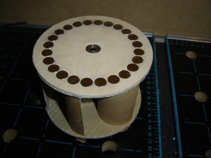
The plates will be fixed directly to the body of the generator, which in this case, is the model 1100 from Renewable Components. As you can see, one will be placed on the top of the generator and the other on the bottom.
The generator is fixed to a mast through the lower tube, through which the winding cables come out, and which at the same time acts as the axis of rotation for the drum that contains the permanent magnets.
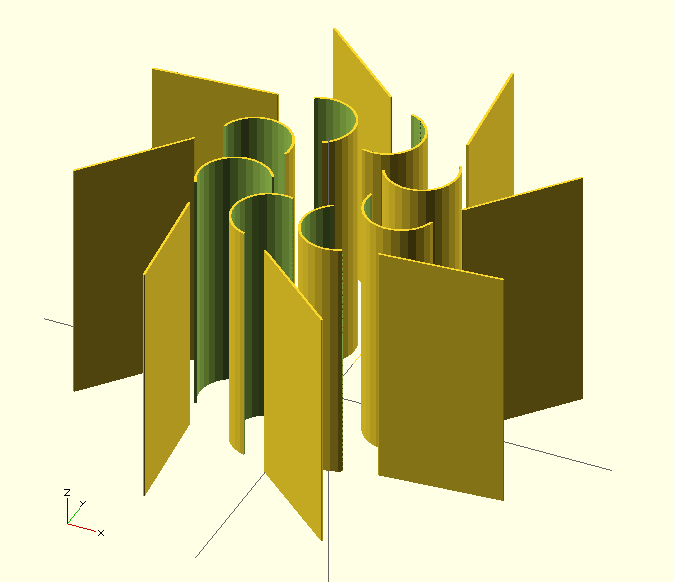
Some conceptual designs made with the help of OpenSCAD.
Prototype Construction.
In this section I will present some of the AeroGenerator prototypes that I am building.
For now, here is the first one, a bit improvised, like the wind tunnel used to make it spin. But it has served to check and adjust the adjustment mechanism of the stator blades. It is made with cardboard and chopsticks for Chinese food.
Now that I have an idea of how to do it, it's time to start looking for more robust materials, such as plywood, threaded rods, etc... and program the cnc to build a more model. ½s robust and works better.
Next, I present the second prototype. Thinner, more stable and more robust than the previous one, with parts manufactured using a homemade CNC milling machine.
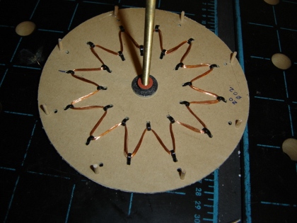
The following video shows the third prototype, which already incorporates a magnetic plate at the base of the turbine and a small winding at the base of the stator, which allows us to appreciate the effects of the opening and closing of the stator. Checking that an adjustable stator allows the generator output voltage to be reduced when it is considered too high on days of excessive wind. Allowing the wind turbine to be kept in operation, without suffering mechanical, electrical and/or electronic damage.
Later we will add the charge regulator (MPPT), and whatever is appropriate, let's go in steps. Although for now we have to get more voltage and more power, but hey, I already have a functional reference.
Use of Permanent Magnet Motors as Generators.
The easiest thing would be to acquire a generator designed for wind turbines, of which we can find 1 kW for about 250 Euros, 2200 W for about 500 Euros, and 1.9 kW for about 650 Euros, even 32 kW for about 2200 Euros, although the latter are designed to work at higher revolutions.
As an alternative, we can use brushless direct current motors (Brushless DC Motors). These motors can be used directly as three-phase generators, since they have 3 windings, which generally have a triangle connector. These brushless motors can be found in lower powers than generators and therefore more economical and practical for experiments with small homemade wind turbines.
For example, to study the behavior of permanent magnet generators at different speeds, we can couple our "generator" to a small direct current motor that we can power using rechargeable batteries or a simple power supply. This will also allow us to experiment with charging voltage regulators at different rotation speeds.
Selecting the motor:
- Nominal voltage. The higher the operating voltage as a motor, the higher the voltage it will provide us with its output operating as a generator.
- Nominal Current. The higher the nominal current, the larger the diameter of the copper wire in its winding, and therefore the fewer losses in its internal resistance.
Modifications. To improve the performance of our wind turbine, we can change the winding for one that allows us to obtain the desired voltages for our working conditions. But first we should study its behavior without modifying anything.
A good way to become familiar with how a motor works as an electricity generator is by building a simple manual generator, that is, powered by a crank, or better, by another motor. With this we can get an idea of the revolutions per minute that we need to obtain the desired output voltage for our application and decide to use a multiplier box and a DC-DC converter to adjust the output voltage of our generator to the application for which it is intended, and will serve as a reference in case we decide to modify the winding, increasing or reducing the number of turns.
For example: With a 12.5 W stepper motor and a step angle of 7.5�, to which I have attached a crank from a manual drill directly to the shaft, I have easily obtained 4.5 RMS volts, at a frequency of 40 Hz, in one of its 4 coils. With which we could obtain about 9 V in continuous with the corresponding rectification and filtering, of the output voltages of its 4 phases, or 2x2, depending on how you look at it.
If we want more output voltage, and therefore more power, we will place a speed multiplier box between the crank and our generator, which provides higher revolutions per minute to the generator.
After playing around a bit, we will have an idea of the revolutions per minute we need to obtain for the desired output voltage. Now, we can start experimenting with wind turbine designs, and look for a model with the appropriate dimensions that provides us with more or less the revolutions per minute that we need for our generator.
When selecting a brushless motor, or BLDCMotor, for our wind turbine, we can determine the approximate main characteristics of operation as a generator from the main characteristics of operation as a motor provided by the manufacturer. That is, if the engine manufacturer offers us a 24 V engine, 4000 rpm without load, we can deduce that working as a generator, at 4000 rpm it will provide something less than 24 V, approximately 21 V.